
Table of Contents
- Why Dynamic Beam Tracking Matters for 6G
- Key Components of a Dynamic Beam Tracking Measurement System
- Measurement Methods for 6G Beam Research
- Challenges at mmWave and Sub-THz Frequencies
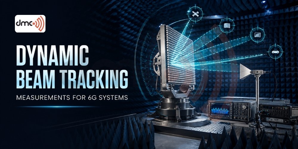
Wireless systems are moving toward higher frequencies, larger antenna arrays, highly directional links, and more adaptive beamforming. As these technologies develop, Dynamic Beam Tracking Measurements for 6G Systems are becoming an important research area for understanding how antenna arrays maintain beam alignment when the channel, device position, or propagation environment changes. DMC USA provides antenna measurement and RF testing solutions that can support controlled evaluation of antenna patterns, OTA performance, and advanced beamforming research.
Why Dynamic Beam Tracking Matters for 6G
Beamforming concentrates RF energy toward a selected direction instead of radiating it equally in every direction. This approach is already fundamental to modern 5G NR systems, where beam management includes procedures for identifying and maintaining suitable spatial directions. 3GPP TS 38.300 provides the overall NR architecture and behavior framework, while detailed physical-layer procedures are specified elsewhere in the 3GPP specification set.
Future 6G research is expected to push these concepts further through larger arrays, higher frequencies, integrated sensing and communication, and potentially sub-THz operation. At shorter wavelengths, small physical movements can produce meaningful changes in the received signal and beam alignment.
Dynamic measurements therefore need to examine more than a static radiation pattern.
Engineers may need to evaluate:
- Beam direction and steering accuracy
- Beam switching behavior
- Gain variation during beam movement
- Tracking performance under controlled motion
- Polarization behavior
- Beamforming consistency across frequency
- OTA performance of integrated antenna systems
- Effects of blockage and changing propagation conditions
Research published in 2026 has specifically investigated adaptive beam tracking for 5G/6G mmWave systems, including the effects of receiver speed and line-of-sight/non-line-of-sight transitions.
From Static Antenna Testing to Dynamic Measurement
Traditional antenna measurements often characterize radiation patterns while the device and measurement geometry remain controlled and stationary. These measurements remain essential because they establish fundamental antenna characteristics.
Dynamic beam tracking measurements add another dimension: time and changing spatial conditions.
Instead of asking only, “Where does the antenna radiate its maximum power?”, engineers can investigate questions such as:
- How quickly can a beam move toward a new target direction?
- How much gain is lost during beam switching?
- Does the main beam remain stable during controlled motion?
- How does performance change when the line of sight is obstructed?
- Can the system identify and maintain an appropriate beam?
A complete measurement strategy can combine static antenna characterization with controlled dynamic experiments.
Key Components of a Dynamic Beam Tracking Measurement System
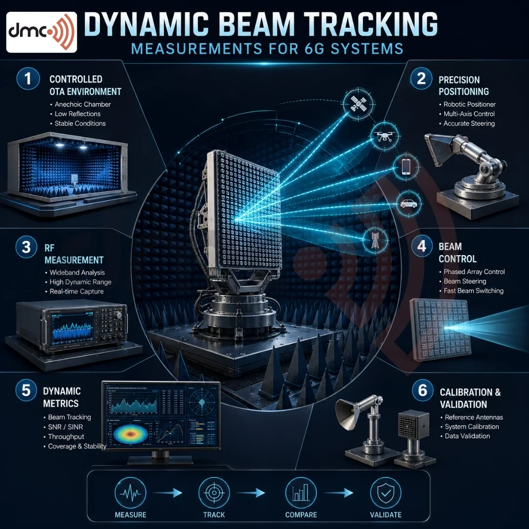
A practical research setup can include several coordinated subsystems.
| Measurement Element | Purpose |
|---|---|
| Anechoic chamber or controlled OTA environment | Reduces unwanted reflections and external RF interference |
| Device under test | Provides the phased-array or integrated antenna system being evaluated |
| Positioning system | Creates controlled angular or spatial movement |
| RF instrumentation | Generates, receives, or analyzes measurement signals |
| Reference antenna/probe | Provides a controlled measurement reference |
| Beam-control interface | Changes beam states or steering commands |
| Measurement software | Synchronizes motion, RF measurements, and beam states |
| Calibration system | Establishes a reliable measurement reference before testing |
The correct architecture depends on the frequency range, antenna aperture, device configuration, measurement distance, required angular coverage, and research objective.
DMC’s antenna measurement systems are designed around requirements such as antenna gain, radiation patterns, OTA evaluation, positioning, RF instrumentation, and controlled test environments.
Measurement Methods for 6G Beam Research
There is no single measurement method that fits every 6G research application.
Near-Field Measurements
Near-field scanning can be useful when chamber size, antenna dimensions, or measurement distance make direct far-field testing impractical. Measured near-field data can be processed to obtain far-field radiation characteristics.
This approach can be particularly useful during antenna and array development.
Far-Field Measurements
Far-field measurements provide direct characterization of radiation patterns when the required measurement distance can be achieved. The basic far-field relationship depends on antenna aperture and wavelength, making the required distance more demanding as antenna size increases and frequency changes.
Compact Antenna Test Range
CATR systems create a controlled plane-wave region inside a relatively compact test environment. They can be useful for high-frequency and OTA measurements where a conventional far-field range would require significant physical distance.
The appropriate method should be selected from the actual antenna size, frequency range, quiet-zone requirement, and measurement uncertainty—not simply because a particular method is associated with 6G.
What Should Be Measured?
Dynamic beam tracking experiments should define measurable performance indicators before testing begins.
Important parameters can include:
- Beam pointing error: Difference between the intended and measured beam direction.
- Peak gain: Maximum measured radiation level for a beam state.
- Beam switching time: Time required to transition between defined beam states.
- Tracking error: Difference between the desired direction and actual beam direction during controlled movement.
- Gain variation: Change in measured gain as the beam tracks a changing direction.
- Side-lobe behavior: Changes in unwanted radiation as beam steering occurs.
- Polarization performance: Stability of polarization characteristics during steering.
- Repeatability: Consistency of results across repeated measurements.
These metrics should be accompanied by a defined calibration procedure and uncertainty analysis.
Challenges at mmWave and Sub-THz Frequencies
Higher-frequency measurements introduce additional practical challenges. Cable losses, connector repeatability, alignment accuracy, calibration quality, chamber reflections, and positioning precision can all influence the result.
At 100 GHz, for example, the free-space wavelength is approximately 3 mm. This illustrates why mechanical alignment that appears insignificant at lower frequencies can become much more important at higher frequencies.
A measurement system should therefore consider:
- Frequency-dependent RF losses
- Calibration stability
- Positioner accuracy
- Probe or reference antenna characteristics
- Chamber quiet-zone performance
- Cable routing
- Thermal and mechanical stability
- Measurement synchronization
DMC’s own 6G antenna measurement guidance highlights the importance of absorber selection, mechanical precision, calibration, and selecting the measurement architecture according to the frequency and antenna under test.
Pro Tip
Do not begin dynamic beam tracking experiments before validating the static measurement chain.
First establish the chamber environment, calibration, reference antenna, position accuracy, RF path, and baseline antenna pattern. Then introduce controlled beam movement and device motion.
This staged approach helps engineers distinguish actual beam-tracking behavior from errors caused by the measurement system itself.
How DMC USA Can Support 6G Measurement Research
A future-ready antenna measurement facility should be designed around the complete research requirement rather than one instrument or frequency band.
DMC USA offers RF and antenna measurement solutions for applications involving defense, aerospace, semiconductor, automotive, wireless technologies, and advanced antenna research. Its solutions can include controlled test environments, absorbers, positioning systems, RF instrumentation, measurement software, calibration, and system integration.
For organizations investigating 6G beamforming, OTA performance, phased arrays, mmWave systems, or emerging sub-THz technologies, a properly designed measurement system can provide the controlled environment needed to compare beam states and understand performance under repeatable conditions.
Conclusion
Dynamic Beam Tracking Measurements for 6G Systems represent an important extension of conventional antenna characterization. As research moves toward higher frequencies, larger arrays, integrated antennas, and more adaptive wireless links, measuring how beams behave over changing spatial conditions becomes increasingly valuable.
DMC USA supports the development of advanced RF and antenna measurement environments for organizations working on today’s wireless technologies and future 6G research.
Frequently Asked Questions
They evaluate how effectively a directional antenna or phased array maintains or changes beam alignment when the target direction, device position, or propagation condition changes.
Higher frequencies and highly directional antenna arrays can make links more sensitive to movement and blockage. Measuring tracking behavior helps researchers understand beam alignment, gain variation, and steering performance.
There is no universal method. Near-field, far-field, CATR, and OTA approaches may be appropriate depending on frequency, antenna size, quiet-zone requirements, and the research objective.
Common parameters include beam pointing error, peak gain, beam switching time, tracking error, gain variation, side-lobe behavior, polarization, and measurement repeatability.
DMC USA provides RF and antenna measurement solutions that can be configured for advanced antenna, OTA, mmWave, and emerging wireless research applications.