
Table of Contents
- Why 6G Requires a New Antenna Measurement System Design
- Step-by-Step: Designing the System
- Common Mistakes Researchers Make
I still remember walking through an anechoic chamber for the very first time. Blue foam pyramids covered every wall, the heavy door sealed shut with a loud hiss, and the unusual silence made even my breathing sound louder. The test engineer smiled and said, “Get used to this room. If you’re working on 6G, you’ll be spending a lot of time here.” He was right. As wireless technologies move into sub-THz and millimeter-wave frequencies, designing an antenna measurement system has become far more challenging. Traditional testing methods are no longer enough, and researchers must build advanced antenna measurement systems capable of delivering the accuracy and precision required for next-generation 6G research.
This is what this article is all about. It’s not the theoretical stuff you’ll find in a textbook, but rather the actual, often messy process of creating the antenna-based measurement systems that will keep pace with research on 6G.
Why 6G Requires a New Antenna Measurement System Design
Antenna measurements aren’t new. Engineers have been analyzing the radiation pattern, gain and polarization for a long time with fairly conventional far-field ranges. The issue is that 6G doesn’t abide according to the old rules.
It’s about frequencies between 24 GHz and all the up to 300 GHz and above huge antenna arrays with numerous elements. Beamforming that alters direction in milliseconds and packaging in which the antenna is directly baked in the silicon chip. In these frequencies, wavelengths decrease to just a few millimeters so even small errors in your test setup could translate into huge measurements mistakes. Cables introduce more loss. Reflections that weren’t significant at 5 GHz now take over your results at 100 GHz. Because 6G devices usually incorporate the antenna into their radio chip (antenna-in-package or AiP) and you’re not able to connect a coaxial probe to test it in the conventional method.
Thus, the measurement system itself is now a research question as well as a supporting tool.
The Core Building Blocks
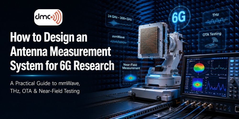
Before you begin bolting things together, you need to know what you’re working with. An antenna measurement system that is typical that is used for research in 6G includes:
- An echo chamber (or small test range) that blocks reflections and the RF noise that is emitted by the surrounding environment.
- A system of precise positioning for the antenna being tested typically a spherical, or cylindrical scanner.
- An analyzer for vector networks (VNA) or Signal generator/spectrum analyzer pair that can operate at the frequency you want to operate.
- Reference antennas and calibration standards.
- Software to detect patterns and near-field-to-far-field transformation and visualization of data.
- To conduct OTA (Over-The-Air) test the probe array is used as a reference horn that is set at a precise distance.
All of them are required at mmWave or sub-THz frequencies. Do not perform the calibration in this case and your gain measurements are off by several dB and you won’t even realize it.
Step-by-Step: Designing the System
1. Determine the frequency range you want to use and your antenna type prior to
Do not purchase equipment prior to deciding whether you’re evaluating a single element or a phased array or an combined AiP module. Each needs a specific chamber size and a different probing strategy.
2. Select between near-field, far-field and compact range designs
This choice will affect the rest of your options, ranging from room sizes to the budget. Refer to the table below for comparisons.
3. Select absorbers rated for your highest frequency
Standard foam absorbers with a pyramidal shape lose their effectiveness at 40 GHz. If you want to work in mmWave or THz it is necessary to use high-performance absorbers designed for those bands or reflections will be a problem for each measurement.
4. Create mechanical precision
At 100 GHz the wavelength of about 3 millimeters. The accuracy of the positioner must be just a percentage of that, and tolerances that are acceptable for sub-6 GHz applications aren’t going to cut it here.
5. Plan your calibration chain
The loss of cables, the repeatability of connectors and phase drift all get more severe at higher frequency. Include calibration in the workflow of your system as a regular step, not a last-minute addition.
6. Automate data acquisition
Manual scanning can be painfully slow when dealing with huge MIMO arrays containing thousands of components. Control of the positioner with scripts and VNA coupled with automated near-field to far-field conversion will save you days of laboratory time.
7. Test with a reference antenna
Before relying on the results of the device you are testing take a measurement of a normal gain horn or a reference antenna that has known characteristics to ensure that your entire chain is functioning.

Comparing Measurement Architectures
| Method | Best For | Typical Frequency Range | Key Advantage | Key Limitation |
|---|---|---|---|---|
| Far-Field Range | Simple, Low-Gain Antennas | Up to ~40 GHz | Straightforward Setup and Analysis | Needs Large Physical Distance |
| Planar Near-Field | High-Gain Directional Antennas | Up to ~110 GHz | Compact Chamber Footprint | Limited Angular Coverage |
| Spherical Near-Field | Full 3D Pattern Characterization | Up to ~110 GHz | Complete Radiation Sphere Data | Slower Scan Times |
| Compact Antenna Test Range (CATR) | mmWave and Sub-THz Arrays | 40 GHz – 300+ GHz | Small Chamber, Plane-Wave Illumination | Reflector Cost and Alignment Sensitivity |
| Over-the-Air (OTA) Testing | Integrated AiP and 5G/6G Devices | 24 GHz – 300 GHz | Tests Real-World Radiated Performance | Requires Probe Calibration |
PRO TIP
Before you purchase a complete test range, conduct an initial feasibility test with an ad hoc near-field setup at the frequency you want to test. This is a fraction of the cost and will reveal issues with calibration and absorbers earlier, well before you decide to invest in the permanent chamber. Many research teams fail to take this step, and discover mechanical alignment issues after the costly equipment is already in place.
Common Mistakes Researchers Make
Some patterns are seen repeatedly in laboratories that are brand new to sub-THz and mmWave testing. Overestimating the loss of cable is one of them and at 100 GHz, even a single cable can consume some dB in signal. Another issue is not taking into account thermal drift. Some amplifiers and VNAs change their performance when the lab heats up over the course of a lengthy test. A surprisingly frequent mistake is ignoring to define the antenna of the probe prior to applying it to a measurement that can cause errors in any test that will follow.
Where This Is Heading
Research in 6G has pushed antenna measurement into areas that was barely existent five years ago. THz-band characterization, reconfigurable smart surfaces (RIS) as well as AI-assisted calibration are becoming the norm at conferences on antenna measurement. Teams who build highly flexible, well-calibrated measurement devices are the ones that can quickly adapt when standards bodies decide on specifications for 6G over the next few years.
The creation of the antenna measuring system that works for 6G isn’t just a once-buy option. It’s an ongoing setup that must evolve along with the research questions you’re asking as well as your frequency bands and the antenna designs that you’re looking for. Make sure you understand the basics, plan your calibration chain meticulously, and be sure to not skip the validation process and the rest of your research will be based on solid ground.
Frequently Asked Questions
An antenna measurement system is a specialized testing setup used to evaluate antenna performance, including radiation patterns, gain, efficiency, and beamforming accuracy. In 6G research, these systems support millimeter-wave and THz frequency testing with high precision.
An anechoic chamber eliminates external interference and RF reflections, creating a controlled environment for accurate antenna testing. This is essential for reliable measurements at high frequencies used in 6G research.
Near-field measurements are performed close to the antenna and use mathematical transformations to calculate far-field performance. Far-field measurements require a much larger testing distance but provide direct radiation pattern measurements for suitable antenna types.
A typical 6G antenna measurement system includes an anechoic chamber or compact antenna test range, a precision positioner, a vector network analyzer (VNA), calibration standards, reference antennas, and software for data acquisition and analysis.
Researchers can improve accuracy by using high-frequency RF absorbers, performing regular calibration, ensuring precise mechanical alignment, automating data acquisition, and validating results with a calibrated reference antenna before testing new devices.