
Table of Contents
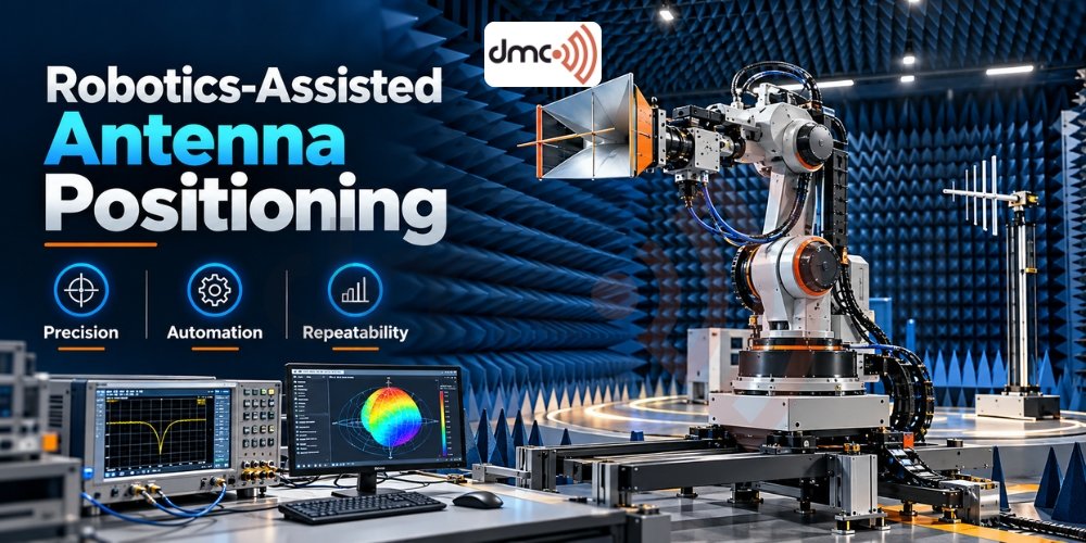
- Robotics-Assisted Antenna Positioning
- How Robotics Works Inside an RF Anechoic Chamber
- Applications of Robotics-Assisted Antenna Positioning
- Key Components to Consider
- Choosing the Right Chamber and Positioning System
Robotics-assisted antenna positioning is changing how engineers approach antenna characterization, automated antenna testing, and repeatable RF measurements. As wireless technologies evolve across automotive radar, telecommunications, aerospace, satellite systems, and the Internet of Things (IoT), testing teams need controlled positioning methods that support consistent measurements across multiple orientations.
Modern antenna measurement chambers combine RF absorbers, shielded structures where required, measurement instruments, antenna positioners, and control software. Robotics can extend these systems by automating movement, coordinating measurement sequences, and reducing repetitive manual adjustments. For Diamond Microwave Chambers Ltd, understanding the relationship between chamber design and robotic positioning is important when planning a reliable antenna measurement environment.
What Is Robotics-Assisted Antenna Positioning?
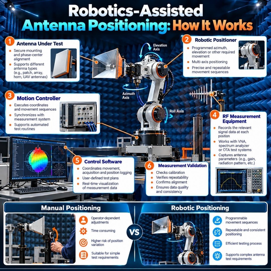
Robotics-assisted antenna positioning uses motorized axes, programmable motion systems, or robotic manipulators to place and orient an antenna under test (AUT) at defined positions. Depending on the application, a system may use a rotary table, azimuth-elevation positioner, linear stage, or multi-axis robotic arm.
The controller follows programmed coordinates while measurement instruments collect relevant RF data. When properly integrated, the positioning system and measurement software can coordinate antenna movement with signal acquisition.
Common capabilities include:
- Automated azimuth and elevation sweeps.
- Programmable angular steps and measurement positions.
- Repeatable positioning sequences.
- Coordinated movement and instrument triggering.
- Automated data collection and test reporting.
The required configuration depends on antenna size, mass, frequency range, measurement geometry, and the intended test method.
Why Modern Antenna Chambers Need Automation
Manual positioning can be sufficient for simple measurements, prototypes, and occasional laboratory tests. However, extensive radiation pattern measurements may require many angular positions and repeated test runs.
Robotic positioning can reduce the need for repeated manual adjustments and help maintain a consistent measurement sequence. It can also make complex test procedures easier to reproduce between operators or product revisions.
Key advantages include:
- Repeatability: Programmed coordinates help reproduce the same movement sequence.
- Workflow efficiency: Automated sweeps can reduce operator involvement during routine measurements.
- Angular coverage: Suitable multi-axis systems can collect data across defined planes or three-dimensional angular regions.
- Test consistency: Standardized motion programs reduce variation caused by manual repositioning.
- Traceability: Position commands, instrument readings, and test settings can be associated within a coordinated workflow.
These benefits depend on proper calibration, stable mounting, suitable software, and verified system performance. Automation alone does not guarantee measurement accuracy.
How Robotics Works Inside an RF Anechoic Chamber
A robotic antenna measurement setup normally combines mechanical positioning, RF instrumentation, motion control, and data processing. Each element has a distinct role.
First, engineers mount the antenna under test on a suitable fixture. The fixture should support the antenna securely without introducing unacceptable electromagnetic disturbance. Next, the positioning controller moves the antenna through programmed angles or coordinates.
A typical sequence includes:
- Install and align the antenna under test.
- Configure the measurement frequency, power, and acquisition settings.
- Define the positioning range and angular step.
- Execute the programmed scan.
- Collect and associate RF readings with position data.
- Process the results and review measurement quality.
The actual procedure varies with the antenna, RF chambers, instrument configuration, and measurement objective.
Applications of Robotics-Assisted Antenna Positioning
Robotic positioning supports several antenna testing applications when the mechanical system and measurement method are appropriate.
1. Antenna radiation pattern measurement
Automated angular scans help characterize how an antenna radiates energy in different directions. Engineers can evaluate beam shape, sidelobes, nulls, and beamwidth from suitable measurement data.
2. Gain and directivity characterization
Positioning systems can support gain-pattern measurements and directivity analysis. Reliable results still depend on the measurement method, reference antennas where applicable, calibration, and the test environment.
3. Over-the-air (OTA) testing
Robotic positioners can support OTA measurements of wireless devices and antennas. Some applications require additional equipment and specific procedures to measure metrics such as total radiated power or total isotropic sensitivity.
4. Automotive radar and aerospace systems
Radar antennas and other directional antennas may require controlled angular scans to evaluate beam characteristics. The system must accommodate the device’s dimensions, mounting requirements, and test geometry.
5. Research and product development
Programmable positioning can help laboratories compare antenna prototypes, investigate design changes, and repeat measurement sequences under consistent conditions.
Key Components to Consider
| Component | Engineering consideration |
|---|---|
| Motion axes | Match azimuth, elevation, linear travel, or other required movement |
| Positioning performance | Verify accuracy, resolution, backlash, and repeatability |
| Mounting fixture | Minimize unwanted movement and electromagnetic disturbance |
| RF cables and connections | Manage cable routing, flexing, phase stability, and connector limits |
| Control software | Coordinate motion, instrument triggering, and measurement data |
| Chamber environment | Account for absorber placement, reflections, clearance, and shielding needs |
| Safety controls | Provide appropriate travel limits, interlocks, and emergency stops |
Selecting a robotics-assisted antenna positioning system requires more than choosing a robot with enough movement axes.
The antenna’s phase center and the positioner’s rotation axes also require careful consideration. If the antenna moves around an unintended point, its distance and orientation relative to the measurement antenna may change, potentially affecting the measured pattern.
Integration Challenges and Practical Solutions
Robotic positioning introduces mechanical and electromagnetic considerations that should be addressed during chamber planning.
Metallic structures, motors, cables, and fixtures can scatter or disturb RF fields. Low-reflectivity or non-metallic mounting components may help, but their suitability must be evaluated for the operating frequency, load, and required mechanical stability.
Cable movement can also affect measurements, particularly when phase information matters. Engineers should plan cable routing, consider suitable rotary joints where continuous rotation is needed, and validate performance throughout the intended motion range.
Before routine testing, verify positioner alignment, coordinate references, instrument calibration, and measurement repeatability. Collision checks and travel limits are important when automated systems move heavy or delicate equipment.
Pro Tip: Validate the Complete Measurement Chain
Do not evaluate a robotic positioner solely by its advertised angular resolution. Check the complete measurement chain, including mechanical repeatability, antenna alignment, fixture effects, cable behavior, instrument calibration, and RF chambers performance.
Run repeated scans using a suitable reference antenna or established verification procedure. Compare the resulting patterns and document differences against predefined acceptance criteria. This helps identify whether observed variations originate from positioning, instrumentation, the antenna, or the chamber environment.
Choosing the Right Chamber and Positioning System
A suitable configuration starts with the measurement objective. Define the operating frequency range, antenna dimensions, required angular coverage, measurement distance, payload, and expected throughput before selecting equipment.
Diamond Microwave Chambers Ltd can be considered when planning an RF test environment where chamber construction, absorber selection, and antenna measurement requirements need to be assessed together. The chamber and positioning system should be specified as a coordinated setup rather than as unrelated purchases.
Discuss the intended test method, required performance, available space, and future expansion plans with the engineering team. Verify that the proposed configuration meets the applicable measurement requirements before finalizing the design.
Conclusion
Robotics-assisted antenna positioning can improve the consistency and efficiency of modern antenna measurement workflows by automating movement and coordinating data collection. Its value depends on selecting appropriate motion hardware, maintaining accurate alignment, controlling electromagnetic interference, and validating the complete test setup.
For organizations developing antennas for wireless, automotive, aerospace, and other RF applications, integrating a suitable robotic positioner with a properly designed measurement chamber can support repeatable and well-documented testing. The best results come from treating automation, chamber performance, calibration, and measurement methodology as parts of one system.
Frequently Asked Questions
It is the use of motorized positioners or robotic systems to move an antenna through programmed orientations for controlled RF measurements.
It can reduce repetitive manual adjustments, standardize scan sequences, and help reproduce measurement positions across repeated tests.
Yes. Suitable systems can collect angular measurement data for two-dimensional or three-dimensional radiation patterns, depending on their axes and test configuration.
No. Accuracy also depends on calibration, alignment, mechanical performance, antenna fixtures, cable effects, instrumentation, and the chamber environment.
Consider frequency range, payload, required axes, angular accuracy and repeatability, measurement distance, RF compatibility, software integration, and safety requirements.