
Table of Contents
- Why Antenna Measurement Matters for UAV Manufacturers
- Essential Antenna Measurement Requirements
- Key Antenna Measurement Requirements at a Glance
- Building a Repeatable UAV Antenna Testing Workflow
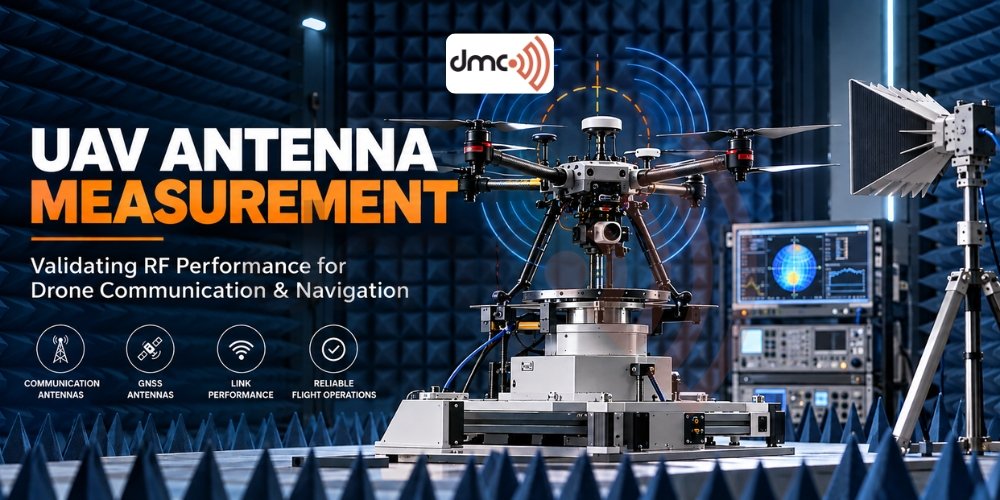
Antenna measurement requirements for UAV and drone manufacturers are essential for evaluating communication performance, navigation reliability and radio-frequency (RF) behaviour. Unmanned aerial vehicles (UAVs) depend on antennas for control links, telemetry, GNSS navigation, video transmission and, in some applications, cellular or satellite connectivity. An antenna that performs well on a workbench may behave differently when installed on a drone because of the airframe, batteries, motors, wiring and other nearby components. Diamond Microwave Chambers Ltd supports RF testing requirements through antenna measurement environments and systems designed for controlled, repeatable measurements.
Why Antenna Measurement Matters for UAV Manufacturers
Drone antennas operate in a compact, electrically complex environment. Carbon-fibre structures, metallic components, cables and electronic assemblies can influence antenna impedance, radiation patterns and efficiency. The extent of these effects depends on the antenna design, operating frequency, materials and installation.
Testing helps manufacturers identify performance limitations before flight trials or product release. It also provides engineering data for comparing antenna designs and checking whether the installed antenna meets defined requirements.
Key benefits include:
- Communication reliability: Evaluate antenna coverage for command, control and telemetry links.
- Navigation performance: Assess GNSS antenna characteristics and installation-related pattern distortion.
- RF integration: Identify interactions between antennas, the airframe and onboard electronics.
- Design validation: Compare prototypes against specified RF performance targets.
- Repeatability: Establish a consistent measurement process across design revisions and production checks.
Antenna testing alone does not guarantee flight safety or regulatory compliance. It is one part of a wider UAV verification programme.
Essential Antenna Measurement Requirements
1. Antenna Radiation Pattern Measurement
A radiation pattern describes how an antenna transmits or receives electromagnetic energy in different directions. For a UAV, this helps engineers understand whether the installed antenna provides suitable coverage as the aircraft changes orientation.
Measurements commonly include azimuth and elevation cuts, with three-dimensional pattern measurements used when a fuller spatial assessment is required. Both peak directions and coverage gaps matter.
Manufacturers should consider:
- Measuring the antenna in its intended installation configuration.
- Recording the test frequency, orientation and measurement conditions.
- Evaluating coverage across the required flight attitudes.
- Checking whether the airframe or nearby components create unexpected nulls.
Antenna patterns should be assessed against the actual communication or navigation requirements rather than assuming that one pattern suits every drone.
2. Antenna Gain and Efficiency
Antenna gain indicates how strongly an antenna directs energy in a particular direction relative to a reference antenna. Efficiency describes how effectively accepted RF power is converted into radiated power, accounting for losses under the relevant definition.
These measurements answer different questions. A high-gain antenna may concentrate energy in certain directions, while a lower-gain design may provide more uniform coverage. Neither is automatically better for every UAV application.
Testing should establish the required gain across relevant frequencies and directions. Where efficiency is important, the method should distinguish radiation efficiency from total efficiency, which also accounts for impedance mismatch.
3. Polarization and Cross-Polarization
Polarization describes the orientation and time-varying behaviour of the electric field. UAV antennas may use linear, circular or other specified polarization arrangements depending on the application.
A mismatch between transmitting and receiving antenna polarization can reduce received signal strength. Cross-polarization measurements can also reveal unwanted radiation in the orthogonal polarization.
Engineers should verify the intended polarization, evaluate the relevant angular range and consider how aircraft banking, pitching and yawing affect the link geometry.
4. Impedance Matching and Return Loss
Impedance measurements help determine how effectively an antenna connects to its RF feed system. A vector network analyser (VNA) is commonly used to measure input reflection coefficient, from which return loss and voltage standing wave ratio (VSWR) can be derived.
Measurements should cover the operating bands and the complete installed RF feed path where appropriate.
- Check resonance and impedance across the required frequency range.
- Inspect connectors, cables and feed points for losses or faults.
- Verify that matching remains acceptable after antenna installation.
- Document calibration, reference planes and test configuration.
Good impedance matching is important, but it does not by itself establish radiation efficiency, coverage or communication range.
5. Over-the-Air (OTA) Testing
OTA testing evaluates antenna or radio-system performance through radiated electromagnetic signals rather than relying only on conducted measurements at a connector. It can help assess the integrated performance of antennas and wireless devices.
Depending on the test objective, measurements may include total radiated power (TRP), total isotropic sensitivity (TIS), radiated patterns or other system-level metrics. TRP and TIS are particularly relevant to applicable wireless-device test methods; they are not mandatory for every drone antenna programme.
The test setup should reflect the applicable radio technology, frequency bands, device configuration and intended measurement method.
Selecting the Right Antenna Test Environment
An anechoic chamber provides a controlled environment for measuring antenna radiation patterns while reducing unwanted reflections from surrounding surfaces. The chamber’s absorber performance, usable frequency range, dimensions and measurement geometry must suit the antenna and test method.
For complete UAV assemblies, manufacturers should consider whether the test facility can accommodate the drone, mounting fixture and required measurement angles. For electrically large antennas or systems, near-field measurement with far-field transformation may be an alternative to a long far-field range. These approaches are established antenna measurement methods described in IEEE Std 149-2021.
6. GNSS and Navigation Antenna Testing
GNSS antennas support satellite-based positioning and timing. Their performance depends on factors such as frequency band, polarization, antenna placement and the surrounding structure.
Testing may examine gain patterns, impedance matching, polarization and installed performance across the required GNSS bands. For applications that require more detailed evaluation, engineers may also investigate multipath susceptibility and the impact of nearby electronics.
A GNSS antenna’s measured gain pattern alone cannot establish positioning accuracy. Receiver design, satellite visibility, interference and the operating environment also influence navigation performance.
7. Electromagnetic Compatibility and Coexistence
UAVs often combine several radios with switching power supplies, motor controllers, digital processors and high-speed data interfaces. These systems can create electromagnetic interference or desensitize nearby receivers.
Testing should therefore consider antenna-to-antenna coupling, conducted and radiated interference, receiver desensitization and coexistence between simultaneously operating radio systems. The appropriate EMC methods depend on the product, operating bands and applicable requirements.
Manufacturers should assess the assembled drone, not just individual components, when integration effects could change the result.

Key Antenna Measurement Requirements at a Glance
| Measurement | What it evaluates | Relevance to UAVs |
|---|---|---|
| Radiation pattern | Angular distribution of radiated energy | Identifies coverage gaps |
| Antenna gain | Directional performance relative to a reference | Supports link-budget analysis |
| Efficiency | Conversion of accepted RF power into radiation | Helps assess antenna losses |
| Impedance and return loss | Matching at the antenna feed | Detects mismatch and integration issues |
| Polarization | Electric-field orientation and characteristics | Supports compatible radio links |
| OTA performance | Radiated behaviour of the integrated device | Evaluates system-level RF performance |
| GNSS antenna performance | Navigation antenna characteristics | Supports positioning-system design |
| EMC and coexistence | Interference and interactions between systems | Helps identify integration risks |
Pro Tip: Test the Antenna in Its Final Configuration
Do not rely exclusively on measurements of an isolated antenna. A drone’s final structure can alter its radiation pattern and impedance.
For meaningful comparisons, use a documented test configuration that records the antenna position, airframe state, cable routing, operating frequency, polarization, calibration procedure and measurement uncertainty. Repeat measurements after significant mechanical or RF design changes.
This makes results more useful for engineering decisions, design verification and production quality checks.
Building a Repeatable UAV Antenna Testing Workflow
A structured test plan helps manufacturers avoid collecting measurements that cannot answer their engineering questions.
- Define requirements: Identify the radio bands, intended coverage, gain targets and relevant regulatory or customer requirements.
- Characterize the antenna: Measure impedance, matching and initial radiation characteristics.
- Evaluate integration: Install the antenna on the representative drone structure and repeat relevant measurements.
- Select the test facility: Confirm chamber dimensions, frequency coverage, positioning capability and measurement method.
- Validate the setup: Check calibration, reference antennas, cable effects, alignment and uncertainty.
- Document results: Record test conditions, plots, deviations and pass/fail criteria established before testing.
Diamond Microwave Chambers Ltd can be considered when planning an appropriate RF measurement environment for antenna characterization. The required chamber configuration and equipment should be selected against the manufacturer’s actual test objectives rather than assuming one setup fits every UAV.
Conclusion
Antenna measurement requirements for UAV and drone manufacturers extend beyond checking whether an antenna transmits a signal. Radiation patterns, gain, efficiency, polarization, impedance, OTA performance, GNSS characteristics and electromagnetic compatibility each address different aspects of RF behaviour.
A well-defined test programme combines appropriate measurement methods with representative installation conditions and repeatable procedures. By evaluating antennas early and retesting after integration changes, drone manufacturers can make better-informed design decisions and identify potential communication issues before field validation.
For organizations developing antenna measurement facilities, Diamond Microwave Chambers Ltd offers a relevant starting point for discussing RF chamber and antenna measurement requirements. The right solution depends on the frequency range, UAV dimensions, accuracy objectives and intended test methods.
Frequently Asked Questions
Common measurements include radiation patterns, gain, efficiency, impedance matching, polarization and, where applicable, OTA performance and GNSS antenna characteristics. EMC and coexistence testing may also be required.
The airframe, wiring, batteries, motors and other antennas can affect RF performance. Installed testing helps reveal changes that isolated antenna measurements may not capture.
An appropriately designed anechoic chamber reduces unwanted reflections, providing a more controlled environment for antenna pattern and other RF measurements. Its suitability depends on the frequency range, test distance, absorber performance and UAV size.
No. Communication range also depends on transmit power, receiver sensitivity, antenna patterns at both ends, propagation conditions, interference, polarization and regulatory limits.
IEEE Std 149-2021 provides recommended practices for antenna measurements, including radiation patterns, measurement facilities and instrumentation. Other requirements depend on the radio technology, product and applicable regulations.