
Table of Contents
- What Are Satellite Antenna Measurements?
- Near-Field Antenna Measurement
- Gain and Radiation Pattern Measurement
- Choosing the Right Measurement Technique
Satellite antennas must deliver predictable gain, radiation patterns, polarization performance, and beam coverage to support reliable communication links. Satellite antenna measurement techniques provide the practical methods engineers use to verify these characteristics before an antenna is deployed in space or integrated into a satellite system.
Depending on antenna size, operating frequency, and measurement objectives, engineers may use far-field, near-field, or compact antenna test range methods.
For organisations developing or validating satellite communication hardware, accurate measurements are important because small errors in gain, pointing, side-lobe levels, or polarization can affect link performance and interference margins. Diamond Microwave Chambers Ltd provides RF and microwave test solutions designed to support controlled antenna measurement environments.
What Are Satellite Antenna Measurements?
Satellite antenna measurements are controlled tests used to characterize the electromagnetic performance of an antenna. Typical parameters include gain, directivity, radiation pattern, beamwidth, side-lobe levels, polarization, efficiency, and impedance.
Antenna measurements can be performed using different test-range configurations. IEEE 149-2021 covers recommended practices for antenna measurements, including measurement facilities, instrumentation, range evaluation, and radiation-pattern measurements.
Important measurement objectives include:
- Measuring maximum antenna gain.
- Mapping co-polar and cross-polar radiation patterns.
- Determining beamwidth and pointing characteristics.
- Evaluating side-lobe performance.
- Measuring polarization characteristics.
- Comparing measured results with simulations.
- Verifying antenna performance against project requirements.
Far-Field Antenna Measurement
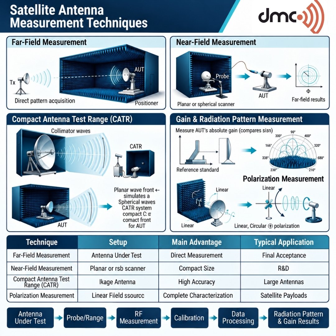
Far-field measurement is one of the most direct satellite antenna measurement techniques. In a far-field setup, the transmitting and receiving antennas are separated by sufficient distance for the electromagnetic wave at the antenna under test to approximate a plane wave.
The commonly used Fraunhofer distance is approximately:
R ≥ 2D²/λ
where R is the measurement distance, D is the largest antenna dimension, and λ is the wavelength.
The required distance can become very large for high-gain or physically large satellite antennas. This is one reason why direct far-field testing can require substantial indoor or outdoor facilities. Field-region behaviour varies with antenna geometry and frequency, so the appropriate measurement configuration should be established during test-range design.
Far-field testing is useful when:
- Adequate measurement distance is available.
- The antenna can be physically accommodated.
- Direct radiation-pattern measurement is preferred.
- High measurement accuracy is required.
Near-Field Antenna Measurement
Near-field measurement overcomes some of the physical limitations of direct far-field testing. Instead of placing the probe at a very large distance, a scanner samples the electromagnetic field relatively close to the antenna.
The measured near-field data can then be mathematically transformed into far-field characteristics.
Common near-field configurations include:
| Technique | Measurement Surface | Typical Advantage |
|---|---|---|
| Planar Near Field | Flat scanning plane | Useful for directional antennas |
| Cylindrical Near Field | Cylindrical surface | Suitable for certain elongated or directional antennas |
| Spherical Near Field | Surrounding spherical surface | Provides comprehensive angular coverage |
| Far Field | Direct measurement distance | Straightforward interpretation when space permits |
| CATR | Collimated test zone | Creates far-field-like conditions in a compact facility |
Modern near-field measurement practice addresses range calibration, probe characteristics, scanning geometry, measurement procedures, and data processing. IEEE’s current P1720 draft specifically covers planar, cylindrical, and spherical near-field measurement practices.
Compact Antenna Test Range
A Compact Antenna Test Range (CATR) uses a reflector system to transform the field produced by a feed into a controlled plane-wave-like test region. This allows engineers to perform measurements under far-field-like conditions without requiring the full physical distance of a conventional far-field range.
CATR systems can be particularly useful for high-frequency antenna testing where the required conventional far-field distance becomes impractical.
A properly designed CATR must control:
- Quiet-zone uniformity
- Amplitude variation
- Phase variation
- Cross-polarization
- Reflections and unwanted scattering
- Reflector performance
For demanding satellite antenna applications, chamber design and range validation are just as important as the measurement instrument itself.
Gain and Radiation Pattern Measurement
Gain measurement determines how effectively an antenna radiates or receives energy in a particular direction compared with a reference. Antenna gain is commonly expressed in dBi relative to an isotropic radiator.
Radiation-pattern measurements show how antenna performance changes with direction. Engineers commonly evaluate:
- Main beam
- Beamwidth
- Side lobes
- Back lobes
- Nulls
- Co-polar response
- Cross-polar response
For satellite systems, radiation-pattern accuracy can be especially important because unwanted side lobes may contribute to interference or reduce frequency-reuse performance.
ITU-R maintains reference and measured-pattern requirements for various satellite and earth-station applications. For example, Recommendation S.465 addresses reference radiation patterns for earth-station antennas in the 2–31 GHz range.
Polarization Measurement
Polarization testing determines how an antenna radiates or receives electromagnetic waves with a particular polarization.
Depending on the satellite application, engineers may investigate:
- Linear polarization
- Circular polarization
- Right-hand circular polarization
- Left-hand circular polarization
- Cross-polar discrimination
- Axial ratio
Polarization errors can reduce the quality of a communication link and increase unwanted coupling between systems. Therefore, polarization measurements should be included when they are relevant to the antenna specification.
Measurement Setup and Calibration
Reliable satellite antenna testing requires more than connecting an antenna to a vector network analyzer. The entire measurement chain needs to be controlled and calibrated.
A typical setup may include:
- Antenna under test (AUT)
- Probe or measurement antenna
- Vector network analyzer or receiver
- Signal source
- Positioner or scanning system
- Control and data-acquisition software
- RF cables and calibration components
- Shielded and absorber-lined measurement environment
Calibration should account for equipment response, cable losses, probe characteristics, positioning accuracy, and other relevant error sources.
Pro Tip: Before starting a full antenna scan, validate the measurement range and calibration using a known reference antenna or established verification procedure. This helps identify systematic errors before valuable test time is consumed.
Choosing the Right Measurement Technique
The best technique depends on antenna size, frequency, required accuracy, available facility space, and the measurement parameters.
For example, a large satellite reflector may make conventional far-field testing impractical, while a near-field system or CATR can provide a more manageable solution. The measurement objective should therefore be defined before selecting the test architecture.
Diamond Microwave Chambers Ltd can support organisations evaluating controlled RF environments for antenna measurement applications, including anechoic chamber and antenna test-system requirements.
Conclusion
Accurate satellite antenna measurement techniques are essential for understanding and validating antenna performance before deployment. Far-field testing provides direct measurements when sufficient distance is available, while near-field techniques use scanning and mathematical transformation to obtain far-field characteristics from measurements made closer to the antenna. CATR systems provide another solution by creating a controlled far-field-like region inside a compact facility.
Gain, radiation pattern, side-lobe level, polarization, and other parameters should be measured according to the antenna’s intended application and applicable technical requirements. By combining appropriate instrumentation, calibration, controlled RF environments, and suitable measurement methods, engineers can obtain dependable data for satellite antenna development and verification.
Diamond Microwave Chambers Ltd provides RF and microwave chamber solutions for organisations requiring controlled environments for antenna and electromagnetic measurements.
Frequently Asked Questions
They are methods used to characterize satellite antenna performance, including gain, radiation pattern, beamwidth, side lobes, polarization, and efficiency.
Far-field testing measures antenna performance at a distance where the wavefront approximates a plane wave. Near-field testing measures the field closer to the antenna and uses mathematical transformation to determine far-field characteristics.
An anechoic chamber reduces reflections and external RF interference, helping engineers obtain cleaner and more repeatable antenna measurement results.
A Compact Antenna Test Range creates a controlled, far-field-like quiet zone within a relatively compact facility, making it useful where conventional far-field distances are impractical.
Common parameters include antenna gain, radiation pattern, beamwidth, side-lobe levels, polarization, cross-polarization, impedance, and efficiency.