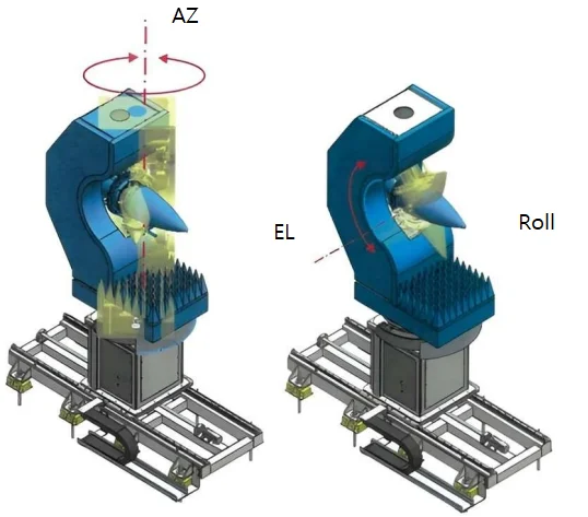
Radome Measurement System with Gimbal Positioner

Radome Measurement System with Gimbal Positioner

Rolled Edge Reflector

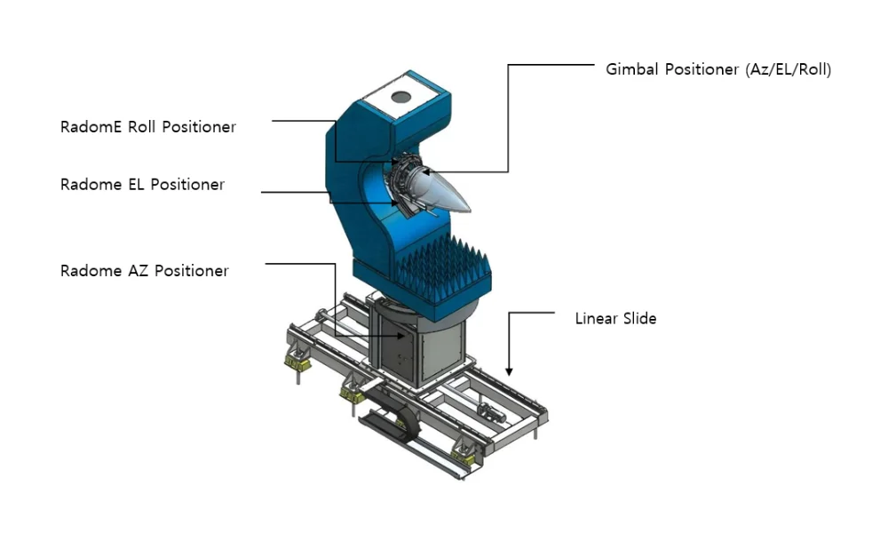
“DMC provides” an Adaptive Radome Diagnostic Systemdesigned for high-precision, economical, and reliable testing and repair of radomes for defense and aerospace applications. It utilizes advanced techniques  to perform high-fidelity measurements of a radome’s effect on an antenna’s performance

ITEM SPECIFICATION
Driving Method AZ : DD Motor
EL/ROLL : Servo Motor + Precision Reducer + Rack
Load Capacity Radome : Max. 30 kg
Drive Range AZ : ±200°
EL : ±56°
ROLL : ±180°
Drive Precision AZ/EL/ROLL : 0.08° RMS
Positioning Repeatability AZ/EL : ±0.01°
Drive Speed AZ : Max. 1.0 RPM
EL : Max. 0.7 RPM
Gimbal Positioner

Gimbal Positioner

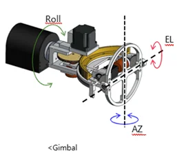
DMC Gimbal Positionerdelivers the uncompromising mechanical accuracy required for next-generation radome and antenna measurement. Featuring high-resolution encoders and three mutually orthogonal axes (Azimuth, Elevation, and Roll), our gimbal precisely simulates real-world flight conditions to quantify boresight error, transmission efficiency, and pattern distortion. When integrated with DMC 360 Software, it ensures fast, reliable, and high-fidelity testing up to 110 GHz, transforming your test range into a precision diagnostic facility.

Key Features to Highlight:

3-Axis Control: Azimuth, Elevation, and Roll for comprehensive coverage.

High Accuracy: Resolution down to 0.025 (per the DMCRF spec sheet).

Integrated Software: Seamless operation with DMC 360 Software for advanced analysis.

Application: Ideal for high-fidelity testing of radome and antenna system

ITEM SPECIFICATION
Drive Method AZ/EL/ROLL : Servo Motor + Precision Reducer + Rack
ROLL : Servo Motor + Worm Reducer
Load Capacity Over 1.0 kg
Drive Range AZ/EL : ±55°
ROLL : ±180°
Driving Accuracy AZ/EL : 0.08° RMS with Load
Drive Speed AZ/EL/ROLL : Over 6°/sec
Encoder Resolution 0.003 / 0.004 Deg
Auto Feeder Changer

Auto Feeder Changer

Rolled Edge Reflector

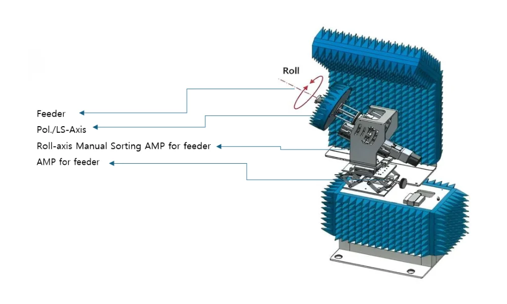
DMC Auto feeder for Gimbal Positioner woks with high Encoder resolution as listed in table with 0.,08 deg RMS with load.

ITEM SPECIFICATION
Drive Method Worm Reducer + Step Motor
Load Capacity 10 kg
Drive Range Continuous 360° Rotation
Location Precision 0.1°
Gimbal Positioner
(Ku)
Moving Range Az ±55˚, El ±55˚, Roll ±180˚
Max. Speed 6 deg/sec
Position Accuracy Azimuth/Elevation 0.08˚ RMS with Load
Repeatability Azimuth/Elevation ±0.02 deg.
Encoder Resolution (Az/El) 0.003 / 0.004 Deg
Max. Load 1 kg
Gimbal Positioner
(Ka)
Moving Range Azimuth ±45°, Elevation ±45°, Roll ±180°
Max. Speed 6 deg/sec
Position Accuracy Azimuth/Elevation 0.08° RMS with Load
Repeatability Azimuth/Elevation ±0.02 deg.
Encoder Resolution (Az/El) 0.003/0.004 Deg
RADOME AUT POSITIONER

RADOME AUT POSITIONER

Rolled Edge Reflector

Key Parameters Tested in Radome Positioners

  • Bore Sight Error: The positioner rotates the radome/antenna assembly in Azimuth (AZ) and Elevation (EL), and the test equipment measures the difference between the true mechanical pointing angle and the actual electrical angle of the transmitted beam.

Impact: Directly affects the radar’s tracking accuracy (i.e., how precisely the radar can determine the location of a target).

  • Transmission Efficiency: The test system measures the received signal power with the radome in place and compares it to the power received without the radome (the reference measurement).

Impact: Directly affects the radar’s maximum detection range. Lower efficiency means less signal is transmitted and less is received.

  • Pattern Distortion:The positioner sweeps the radome/antenna assembly across the desired angular range, and the test equipment maps the full 3D radiation pattern, focusing on the strength of the side lobes relative to the main beam.

Impact: Increased side lobes can make the radar susceptible to jamming or cause it to detect energy from unwanted directions.

ITEM SPECIFICATION
Driving Method LM Guide + Ball Screw + Servo Motor
Driving Range 1.4m
Item Description Specification
Radome Positioner Max Load 30kg
Moving Range Az ±200˚, El ±56˚
Gimbal Roll ±180˚
Radome Roll ±180˚
Tx Pol ±180˚
Max Speed Azimuth 1.0 RPM
Elevation 0.7 RPM
Slide 1.4m

Frequently Asked Questions

A radome test gimbal positioner is a precision positioning system used to rotate and position radomes and antenna assemblies during RF and antenna measurement tests.

It is used to evaluate how a radome affects antenna performance, including boresight error, transmission efficiency, and radiation pattern distortion.

The system provides three-axis control, including Azimuth (AZ), Elevation (EL), and Roll, enabling comprehensive angular testing of radome and antenna systems.

Boresight error is the difference between the mechanical pointing direction and the actual electrical direction of the transmitted antenna beam. It can directly affect radar tracking accuracy.

Transmission efficiency is measured by comparing the received signal power with the radome installed against a reference measurement taken without the radome.

Yes. The positioner can sweep the radome and antenna assembly through the required angular range to help measure and analyze radiation pattern distortion, including changes to sidelobe performance.

The system specifications include a driving accuracy of 0.08° RMS with load and high-resolution encoders for precise radome and antenna positioning.

The radome positioner can support a maximum load of up to 30 kg, depending on the system configuration.

When integrated with the DMC 360 software and an appropriate test configuration, the gimbal system supports high-fidelity testing at frequencies up to 110 GHz.

Yes. The system can be configured based on application requirements, including radome size, load capacity, angular movement, positioning accuracy, and antenna measurement requirements.

What Our Clients Say

There are no reviews yet. Be the first one to write one.