
Table of Contents
- Automotive Chamber Size Guide: From ECU Bench Tests to Full Vehicles
- Why Does Automotive Chamber Size Matter?
- Automotive EMC Chamber Size Guide
- Key Factors to Consider Before Selecting a Chamber
equipment configurations, and customer requirements.An automotive chamber should not be selected by physical dimensions alone. The required frequency range, applicable test method, equipment under test (EUT), antenna distance, quiet-zone requirements, and future testing plans all influence the final design.
Why Does Automotive Chamber Size Matter?
The electromagnetic environment in which automotive electronics function is becoming more complicated.ECUs, sensors, infotainment systems, battery management systems, advanced driver-assistance systems (ADAS), and wireless connectivity modules can experience or generate electromagnetic interference.
An appropriately designed chamber helps create a controlled environment for evaluating emissions,immunity, and other specified RF test requirements. The chamber must accommodate the equipment under test while providing the required electromagnetic environment.
Key considerations include:
- Test object dimensions: The size and configuration of the component or vehicle.
- Test method: Whether the application involves conducted tests, radiated emissions, radiated immunity, or antenna measurements.
- Measurement distance: The required separation between the antenna and the equipment under test.
- Shielding performance: The attenuation required to limit external electromagnetic interference.
- Absorber performance: The frequency-dependent requirements for reducing unwanted reflections.
- Accessibility: Space for technicians, cables, fixtures, robotic systems, and maintenance.
A chamber that is too small may restrict antenna placement or prevent the intended test configuration. An unnecessarily large chamber, meanwhile, can increase construction, absorber, facility, and operating costs.
Automotive EMC Chamber Size Guide
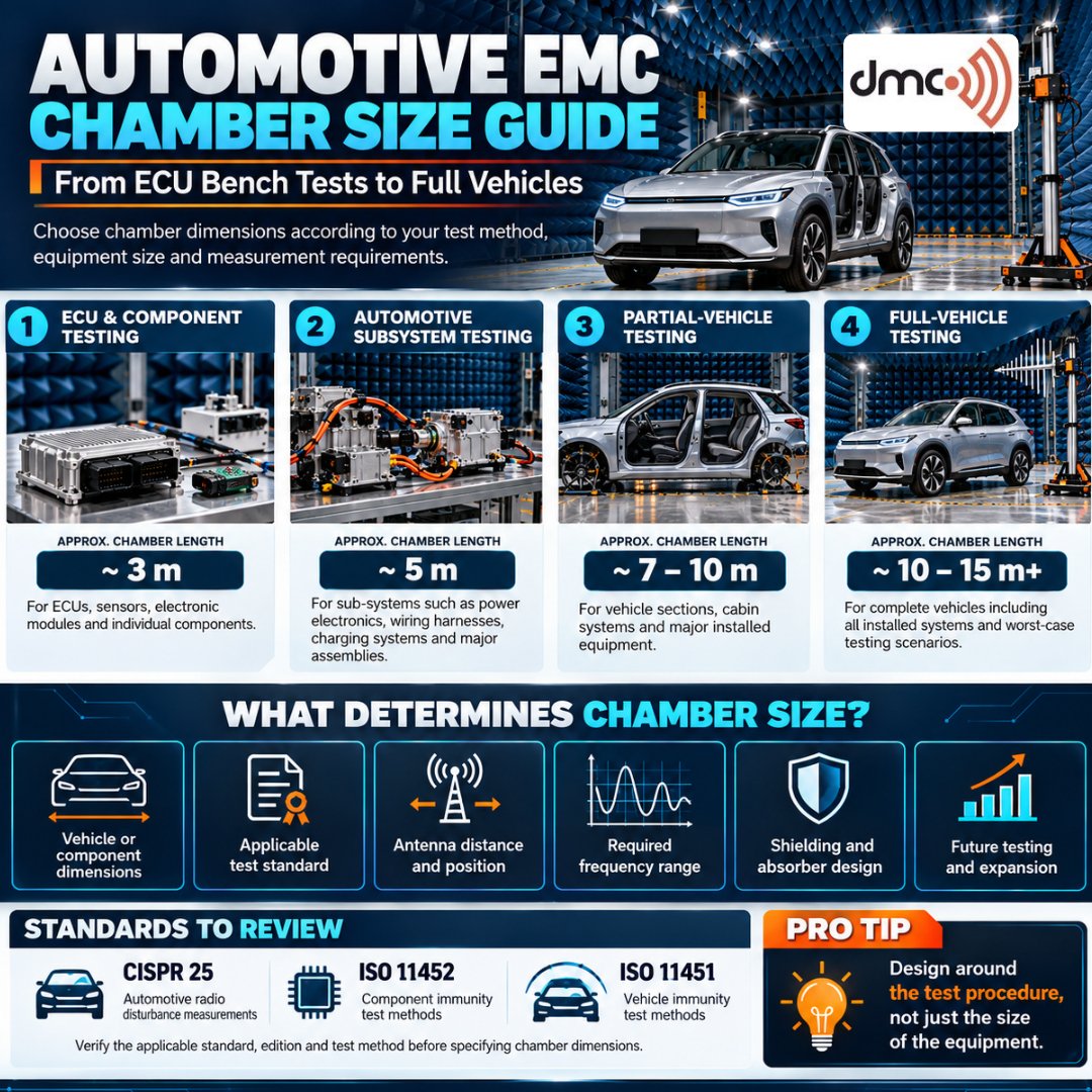
The following table provides illustrative preliminary planning ranges, not universal standard dimensions or guaranteed product specifications. The test technique, vehicle envelope, antenna distance, absorber configuration, and necessary test volume all affect the actual interior dimensions.
1. ECU and Component Testing Chambers
Compact shielded rooms or suitably equipped EMC test facilities are frequently used to test ECUs and smaller vehicle electronic components. A chamber with an internal length of approximately 3 m may be suitable for some component-level applications, but the actual requirement depends on the prescribed test setup.
Common applications include:
- Engine and transmission control modules.
- Battery management and power electronics controllers.
- Automotive sensors and communication modules.
- Infotainment and telematics electronics.
- Individual electronic assemblies and wiring components.
The chamber design should consider the required ground plane, cable routing, support fixtures, antenna arrangement, and equipment access. For automotive component tests, standards such as CISPR 25 and the relevant parts of ISO 11452 may apply, depending on the test being performed.
2. Subsystem Testing Chambers
Subsystem testing involves larger assemblies than a single ECU. Examples include wiring harnesses, power electronics assemblies, battery-related equipment, and integrated automotive electronic systems.
A chamber with an internal length of approximately 5 m may be a useful initial planning reference for selected applications. However, a large battery assembly or extended wiring harness may require a different configuration.
Important design requirements include:
- Sufficient space around the complete assembly.
- Appropriate grounding and test fixtures.
- Defined antenna positions and measurement distances.
- Safe access to the equipment under test.
- Adequate absorber coverage for the intended frequency range.
The chamber must be designed around the actual test procedure rather than the subsystem’s dimensions alone.
3. Partial-Vehicle Testing Chambers
Partial-vehicle testing may involve a vehicle cabin, instrument panel, seating area, powertrain assembly, or another substantial vehicle section.
For some settings, an indicated internal length of 7–10 m could be taken into consideration. The required dimensions depend on the size of the assembly, the test method, antenna positioning, and the space needed to operate measurement equipment.
At this stage, chamber planning should include:
- Clearance for the full test assembly and its supports.
- Antenna positioning and movement requirements.
- Cable penetrations and service connections.
- Access for installation, maintenance, and troubleshooting.
Early coordination between the chamber designer and the EMC test team can reduce the risk of costly layout changes.
4. Full-Vehicle EMC Testing Chambers
Full-vehicle chambers accommodate complete cars, light commercial vehicles, or other vehicle platforms,depending on the facility design. An internal length of approximately 10–15 m or more can serve as an initial planning range for selected passenger-vehicle applications.
The final dimensions must account for the actual vehicle envelope, including its length, width, height, and test position. Adequate clearance is also needed for the antenna system, absorber arrangement, measurement equipment, and technician access.
Full-vehicle test facilities may support specified radiated emissions, immunity, or other automotive RF procedures. Depending on the intended tests, relevant requirements may come from CISPR 12, ISO 11451, or applicable vehicle regulations such as UN Regulation No. 10 (ECE R10).
These standards address different test scopes and should not be treated as interchangeable. The applicable requirements must be confirmed for the specific vehicle category, test method, and regulatory objective.
Key Factors to Consider Before Selecting a Chamber
1. Applicable test standards
Identify the exact standards, editions, test levels, frequency ranges, and methods required by your customers or regulatory programme. Not every chamber needs to support every automotive test.
2. Internal dimensions and clearances
Consider the complete EUT, support equipment, antenna positions, cables, fixtures, and safe access.Usable internal space is more important than the external footprint alone.
3. Shielding effectiveness
The test environment and facility specifications determine the necessary shielding performance. Establish the target attenuation across the relevant frequency range and define how shielding performance will be verified.
4. RF absorber selection
RF Absorber material and layout influence reflections and test performance. The correct solution depends on the frequency range, incidence angles, power handling, fire requirements, and intended test method.
5. Antenna and positioning systems
Some applications require fixed antenna positions, while others benefit from turntables, antenna masts,automated positioning, or other repeatable movement systems. These requirements affect both the layout
and budget.
6. Expansion and future requirements
Plan for anticipated vehicle platforms, new test procedures, additional equipment, and changing frequency requirements. Any future-proofing should be based on realistic engineering needs.
Pro Tip
Design the chamber around the test procedure, not just the size of the vehicle or component. Before requesting a quotation from DMC, prepare a list of applicable standards,frequency ranges, EUT dimensions, antenna distances, shielding targets, and planned future tests. This helps the engineering team determine the required internal dimensions and avoid unnecessary redesign or overspending.
Conclusion
The right automotive chamber size depends on whether you are testing an individual ECU, a larger electronic subsystem, a partial vehicle, or a complete vehicle. Indicative dimensions of 3 m, 5 m, 7–10m, and 10–15 m or more can help establish an initial planning framework, but they are not universal requirements.
By assessing the relevant standards, test methods, EUT dimensions, antenna positions, shielding performance, absorber design, and future needs, engineering teams can select a chamber that fits their real testing objectives. Working with an experienced chamber supplier such as Diamond Microwave Chambers Ltd can help translate those requirements into a practical chamber design.
Frequently Asked Questions
A chamber with an internal length of around 3 m may suit selected ECU and component tests. The actual dimensions depend on the test procedure, equipment configuration, antenna arrangement, and applicable standard.
An internal length of approximately 10–15 m or more can be an initial planning reference for some passenger vehicles. The final design must account for vehicle dimensions, test distances, antenna positions, and the required test volume.
Relevant standards may include CISPR 25 for radio disturbance measurements and ISO 11452 for component immunity testing. ISO 11451 addresses vehicle immunity test methods. The applicable standard depends on the test objective and the required edition.
A facility can be designed to support multiple test applications, but a small component chamber generally cannot accommodate a complete vehicle. Shared facilities require careful consideration of chamber dimensions, antenna arrangements, absorber configuration, and each test method’s requirements.
Start by defining the equipment under test, applicable standards, frequency range, test levels, antenna distances, shielding requirements, and expected future applications. Share these requirements with the chamber manufacturer before finalising the design.