
Table of Contents
- What is Anechoic Chambers Shielding?
- What Happens to RF Energy Inside the Chambers?
- Why Cable Penetrations Need Special Attention
- Why Choose Diamond Microwave Chamberss Ltd?
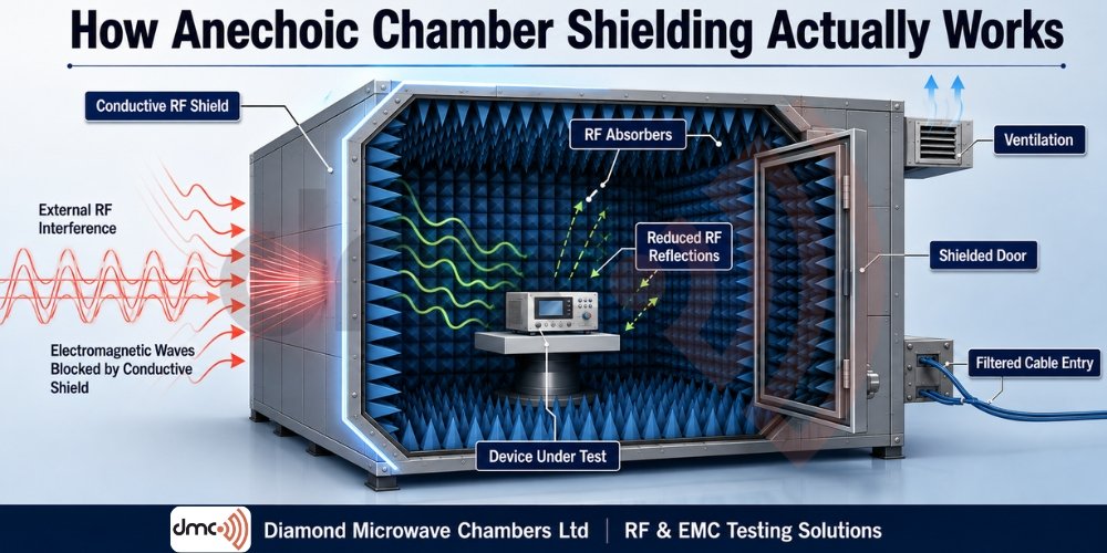
When engineers think about an anechoic chambers, they often picture a room covered with pyramid-shaped absorbers. However, those absorbers are only one part of the system. Anechoic chambers shielding depends on the combined performance of the conductive enclosure, doors, seams, cable penetrations, ventilation, grounding and internal RF absorbers.
The primary purpose of shielding is to prevent unwanted electromagnetic energy from entering the test environment and interfering with measurements. At the same time, the chambers must prevent internally generated RF energy from escaping into the surrounding environment.
For companies carrying out EMC, antenna, RF or microwave testing, understanding how this shielding works helps explain why chambers construction details matter so much.
What is Anechoic Chambers Shielding?
Anechoic chambers shielding is the process of creating a controlled electromagnetic environment using a conductive enclosure around the test area.
The outer conductive structure works on the principles of electromagnetic shielding. Depending on the field and frequency, shielding can involve reflection, absorption and multiple internal reflections within the shielding material.
In an RF anechoic chambers, however, shielding alone is not enough. A conventional metal enclosure can block outside signals but still reflect electromagnetic energy generated inside the chambers.
This is why an anechoic chambers combines:
- A conductive RF shield
- RF absorbing materials
- Shielded doors
- Filtered power and signal connections
- Controlled ventilation
- Proper bonding and grounding
- Carefully designed test geometry
Together, these elements create a low-reflection environment suitable for accurate measurements.
How Does the Metal Shield Work?
The outer shell of an anechoic chambers can be understood as a large conductive enclosure or Faraday-cage structure.
When an electromagnetic wave reaches a conductive shield, the electric field interacts with the free charges in the conductor. A portion of the incident energy can be reflected, while another portion can be absorbed within the material.
Shielding effectiveness therefore depends on factors such as:
- Material conductivity
- Shield thickness
- Frequency
- Construction quality
- Seams and joints
- Openings and penetrations
- Door design
- Cable and ventilation treatment
The important point is that a chamber does not become an effective shield simply because its walls are made from metal. The entire enclosure must maintain electrical continuity.
Why Seams and Doors Matter
One of the most important aspects of anechoic chambers shielding is controlling openings in the conductive enclosure.
A small gap, poorly bonded joint or damaged door seal can create a path for electromagnetic energy to enter or escape. This becomes particularly important as operating frequency increases because smaller physical discontinuities can become electrically significant.
RF doors therefore use specialised conductive sealing arrangements to maintain continuity when closed.
Similarly, chambers panels must be assembled and bonded correctly so that the enclosure behaves electrically as a continuous shield.
This is why chambers design and installation quality are just as important as selecting the right shielding material.
What Happens to RF Energy Inside the Chambers?
This is where RF absorbers become essential.
The conductive walls prevent external electromagnetic signals from easily entering the chambers, but metal surfaces naturally reflect RF energy. Those reflections could interfere with measurements.
RF absorbers are installed on chambers surfaces to reduce these reflections.
Common absorber designs use lossy materials, often in tapered or pyramidal structures. Their geometry helps electromagnetic energy enter the material, where losses convert part of the RF energy into heat rather than allowing it to return strongly into the test area.
The absorber’s performance depends on factors including:
- Operating frequency
- Absorber thickness and geometry
- Material properties
- Angle of incidence
- Polarisation
- Installation method
This means absorber selection cannot be separated from the chambers’s intended application.
Shielding vs Absorption: What Is the Difference?
These two functions are often confused.
| Feature | Shielding | RF Absorption |
|---|---|---|
| Main purpose | Blocks or attenuates external/internal RF transmission | Reduces internal reflections |
| Typical location | Chambers enclosure | Interior surfaces |
| Main principle | Reflection and absorption in conductive material | Dissipation of RF energy |
| Protects against | External electromagnetic interference | Reflections and multipath effects |
| Important factors | Seams, doors, penetrations and bonding | Frequency, geometry and material |
| Main benefit | Controlled electromagnetic isolation | Improved measurement environment |
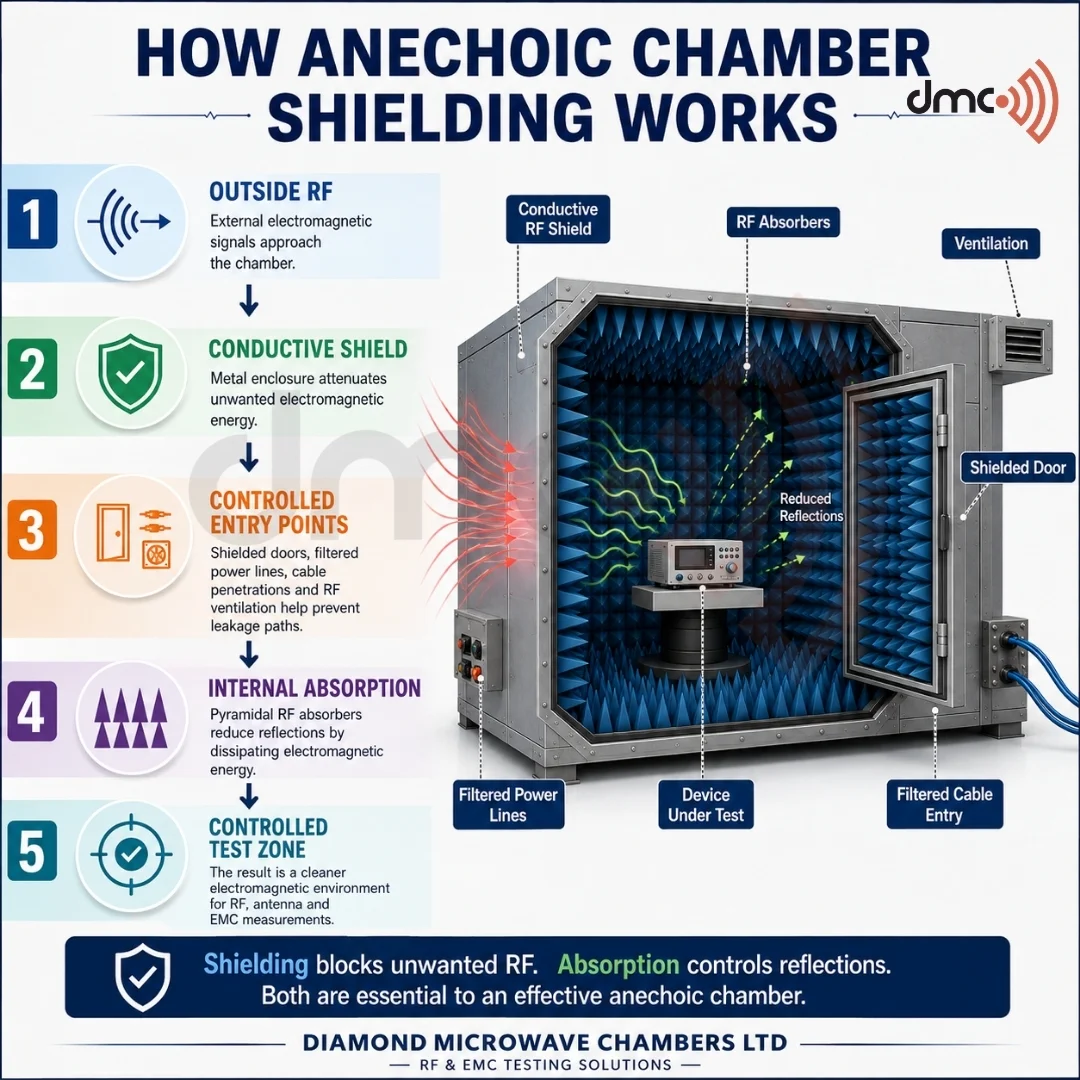
A good anechoic chambers requires both functions to work together.
Why Cable Penetrations Need Special Attention
A chambers can have excellent walls and still suffer from poor shielding performance if cables are not properly treated.
Power, control and measurement cables can provide unwanted electromagnetic paths through the shield. For this reason, chambers systems may use filtered electrical penetrations, shielded connectors and appropriate bulkhead interfaces.
The penetration itself also needs to maintain the electrical integrity of the enclosure.
Other services require similar consideration. Ventilation systems, for example, cannot simply use an ordinary open grille because that would create an electromagnetic opening.
Specialised RF ventilation structures can allow air movement while providing attenuation of electromagnetic energy.
The Role of Grounding and Bonding
Grounding and bonding are important parts of a chambers’s overall electrical design.
Bonding provides electrical continuity between conductive components, including panels and other sections of the shield. The objective is to prevent unintended discontinuities that could compromise shielding performance.
Grounding, meanwhile, connects the chambers system to the required electrical reference and safety infrastructure.
It is important not to treat grounding as a substitute for good shielding construction. The chambers must first have a properly designed conductive enclosure, with bonding and penetration treatment appropriate to the intended performance.
How Chambers Shielding Supports Accurate Testing
The objective of anechoic chambers shielding is ultimately measurement quality.
External RF signals can raise the background electromagnetic environment and interfere with sensitive measurements. Internal reflections can also combine with the direct signal and create measurement errors.
A properly designed chambers addresses both problems:
Outside interference → Conductive shield → Controlled test environment
Internal RF energy → RF absorber → Reduced reflections
This combination helps create a controlled environment where engineers can characterise equipment, antennas and electromagnetic behaviour with greater confidence.
Anechoic chambers are used for applications including antenna measurements, EMC testing, radiated emissions and radiated immunity testing.
Key Factors to Consider When Designing Shielding
Before selecting an anechoic chambers, engineers should consider the complete testing requirement rather than focusing only on the chambers’s physical dimensions.
Important considerations include:
- Required operating frequency range
- Required shielding effectiveness
- Required quiet-zone size
- Type and size of equipment under test
- Antenna configuration
- Test distance
- Absorber performance
- Door requirements
- Power and signal penetrations
- Ventilation requirements
- Applicable testing standards
- Installation and maintenance requirements
The chambers should be designed around the measurement objective.
Pro Tip
Don’t evaluate an anechoic chambers by looking at the absorber material alone. Ask how the complete system performs—including shielding joints, doors, penetrations, ventilation, absorber characteristics and the required quiet zone.
A chambers with excellent absorbers can still deliver poor results if the conductive enclosure has leakage paths or the test environment has not been properly designed.
Why Choose Diamond Microwave Chamberss Ltd?
Designing an effective anechoic chambers requires more than assembling metal panels and RF absorbers. The enclosure, absorber system, access points and supporting services must work together as one electromagnetic environment.
Diamond Microwave Chamberss Ltd provides expertise in microwave and EMC chambers solutions, helping organisations develop controlled environments for demanding RF and electromagnetic testing applications.
The right chambers should be selected according to the required frequency range, test method, equipment, quiet-zone requirements and performance objectives—not simply its size or appearance.
Conclusion
Anechoic chambers shielding works through a combination of electromagnetic isolation and controlled absorption.
The conductive enclosure helps prevent unwanted RF energy from crossing the chambers boundary, while internal RF absorbers reduce reflections from the chambers surfaces. Doors, seams, cables, ventilation and bonding are equally important because every opening or discontinuity can affect the overall electromagnetic environment.
Understanding these principles makes it easier to evaluate chambers performance and select a solution that matches the actual testing requirement.
For reliable RF and EMC testing, anechoic chambers shielding is not one component—it is a complete system.
Frequently Asked Questions
Anechoic chambers shielding is the use of a conductive enclosure and supporting components to reduce unwanted electromagnetic signals entering or leaving the test environment.
Not primarily. RF absorbers are mainly used to reduce reflections inside the chambers. The conductive enclosure provides the principal shielding function.
Metal walls provide a conductive barrier that attenuates electromagnetic energy and helps isolate the test environment from external RF interference.
Yes. Cables passing through the chambers boundary can create RF leakage paths if they are not properly filtered, shielded or integrated into the chambers penetration system.
Performance is normally evaluated through appropriate electromagnetic measurements and acceptance testing against the requirements specified for the chambers and its intended application. Chambers performance can also require periodic verification depending on the facility and applicable requirements.