
Table of Contents
- Choosing Chamber Dimensions Without the Test Requirement
- Positioning Antennas Too Close to Surfaces
- Forgetting Cable and Penetration Design
- Poor Coordination Between Chamber Components
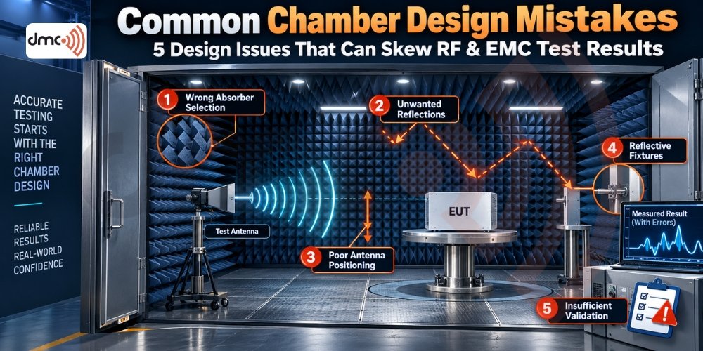
A well-designed anechoic chamber should create a controlled electromagnetic environment where reflections, external interference, and unwanted interactions are minimized. However, even a professionally constructed EMC testing chamber can produce unreliable measurements when design details are overlooked. Problems with absorber selection, chamber dimensions, antenna positioning, shielding, floor construction, fixtures, or validation can introduce unwanted reflections and measurement uncertainty.
For companies investing in an RF test chamber, these issues matter because a chamber is not simply a shielded room covered with absorbers. Its dimensions, materials, internal configuration, equipment and operating procedures all work together to determine measurement performance. DMC technical guidance specifically identifies reflections, absorber behavior, antenna interactions and mounting structures as factors that can influence chamber measurements.
Choosing Chamber Dimensions Without the Test Requirement
One of the most important anechoic chamber design decisions is determining the internal test volume. Designing the room first and deciding the testing requirements later can create problems with measurement distance, antenna positioning, equipment clearance and frequency coverage.
The chamber must provide enough usable space for the intended equipment and measurement geometry. If the test distance is too short, the required measurement condition may not be achieved. Similarly, insufficient clearance around the equipment under test (EUT) can increase unwanted electromagnetic interactions.
Before finalizing dimensions, consider:
- Required frequency range
- Measurement distance
- EUT dimensions and weight
- Antenna dimensions
- Turntable requirements
- Absorber thickness
- Equipment access
- Required test configuration
The objective is not simply to build a larger chamber. It is to build a chamber whose usable test volume supports the intended measurements.
Using the Wrong RF Absorber Configuration
Absorbers are critical components of an EMC chamber because they reduce reflections from internal surfaces. However, selecting absorber material based only on appearance, thickness or price can create performance gaps.
Different absorber technologies have different frequency characteristics. Ferrite, pyramidal foam and hybrid absorber configurations may be selected according to the required frequency range and chamber design.
A common design mistake is assuming that one absorber type will provide identical performance across the entire operating range.
Check:
- Frequency-dependent absorber performance
- Required reflectivity characteristics
- Absorber thickness
- Wall, ceiling and floor coverage
- Mechanical durability
- Installation consistency
- Compatibility with the chamber’s validation requirements
Leaving Reflection Paths Untreated
Small reflective components can have a surprisingly large effect on measurements. Internal lighting, cameras, safety systems, antenna supports and other hardware can become unintended scattering objects.
DMC guidance specifically identifies internal objects such as lighting, cameras and safety circuits as potential sources of extraneous reflections.
This means the chamber design should consider the complete internal environment rather than focusing only on the major walls.
A good design should minimize unnecessary conductive or reflective structures within the test volume.
Ignoring the Floor and Turntable
The floor is another common source of chamber design problems. In a semi-anechoic chamber, the floor configuration is part of the measurement environment. In a fully lined chamber, the floor also requires careful consideration because access structures and supporting surfaces can affect RF behavior.
DMC documentation notes that practical floor constructions can become electrically visible during chamber verification, potentially requiring construction modifications.
Turntables and antenna mounts also require attention. Their materials, dimensions and position can interact with the electromagnetic field.
Therefore, chamber designers should evaluate:
| Design Area | Potential Problem | Possible Effect |
|---|---|---|
| Chamber dimensions | Insufficient test volume | Incorrect measurement geometry |
| RF absorbers | Wrong frequency performance | Increased reflections |
| Floor | RF-visible construction | Measurement variation |
| Turntable | Reflective or unsuitable material | Pattern distortion |
| Antenna mount | Excessive interaction | Gain/pattern changes |
| Fixtures | Poor positioning | EUT interaction |
| Shielding | Leakage or discontinuities | External interference |
| Internal hardware | Uncontrolled reflections | Measurement uncertainty |
Positioning Antennas Too Close to Surfaces
Antenna positioning is not simply a matter of placing the antenna at the required distance. Nearby absorbers, conductive structures, fixtures and other antennas can influence antenna behavior.
DMC documentation identifies mutual coupling and imaging effects as possible contributors to changes in antenna characteristics, including detuning, gain variation and radiation-pattern distortion.
This is especially important when designing an antenna test chamber for precise radiation measurements.
The design should maintain appropriate clearance and provide stable, repeatable antenna positioning. The mounting structure should also remain mechanically rigid so that the antenna does not move during testing.
Treating Shielding as an Afterthought
A chamber may contain high-performance absorbers, but absorbers cannot compensate for fundamental shielding problems.
Shielding continuity must be considered around:
- Doors
- Cable penetrations
- Ventilation openings
- Power entry points
- Waveguides
- Filters
- Seams and joints
A small weakness in the shielding system can allow external electromagnetic signals to enter the chamber or test signals to escape.
For this reason, shielding design and absorber design should be treated as interconnected but separate engineering requirements.
Forgetting Cable and Penetration Design
Cables entering the chamber can become unintended pathways for conducted or radiated interference. Poorly designed penetrations can compromise shielding performance and create repeatability problems.
Power, signal, data and control connections should therefore be planned during the chamber design stage.
The correct approach depends on the equipment and testing requirements, but common considerations include filtered interfaces, appropriate shielding, controlled cable routing and suitable penetration systems.
Skipping Proper Chamber Validation
One of the biggest mistakes is assuming that a chamber performs correctly simply because construction is complete.
A chamber needs appropriate verification or validation against the requirements applicable to its intended use. Measurement methods can reveal reflection problems, field non-uniformity and other issues that are difficult to identify through visual inspection alone.
DMC technical material discusses verification procedures and uncertainty contributions associated with absorber reflectivity, antenna interactions and other chamber effects.
Validation should assess the actual installed chamber rather than relying solely on component specifications.
Pro Tip
Design the chamber around the measurement—not around the room.
Before construction begins, define the frequency range, measurement distance, EUT dimensions, antenna requirements, absorber configuration, shielding interfaces and validation method. This approach helps identify design conflicts before they become expensive modifications.
Failing to Consider Future Testing Requirements
Another common EMC chamber design mistake is designing only for today’s product.
Testing requirements can evolve as products become more complex and operating frequencies increase. A chamber designed with no allowance for future equipment, larger EUTs, additional antennas or expanded frequency coverage may become restrictive.
A practical design review should therefore consider potential future requirements without unnecessarily increasing project cost.
Poor Coordination Between Chamber Components
Finally, chamber performance depends on how the individual components work together.
Shielding, absorbers, doors, ventilation, turntables, antenna systems, fixtures, cable penetrations and measurement equipment should not be designed as isolated components.
Diamond Microwave Chambers Ltd approaches chamber projects as integrated engineering systems, where the intended test application determines the chamber configuration, materials and supporting systems.
When the design process considers these interactions from the beginning, the risk of unexpected reflections, interference and repeatability problems can be reduced.
Conclusion
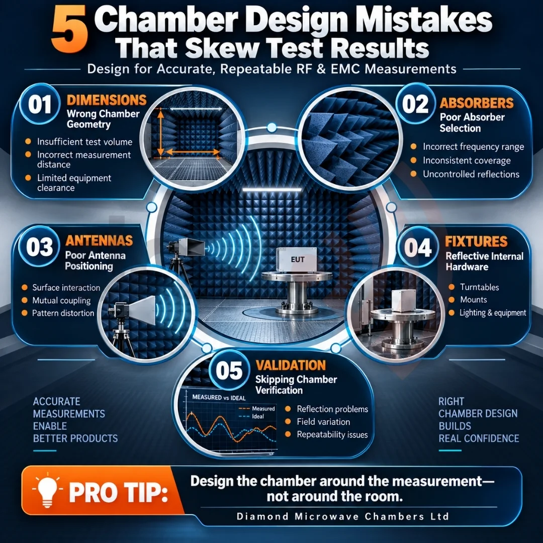
Accurate EMC and RF measurements depend on more than installing absorbers inside a shielded enclosure. Common chamber design mistakes often originate from decisions made before construction, including incorrect dimensions, unsuitable absorber configurations, poor antenna positioning, reflective fixtures, inadequate shielding interfaces and insufficient validation.
A properly engineered EMC chamber design should begin with the testing objectives and work backward to determine the chamber geometry, absorber system, shielding architecture, equipment layout and validation approach.
For reliable and repeatable results, Diamond Microwave Chambers Ltd can help organizations plan and develop RF and EMC test environments around their specific testing requirements.
Frequently Asked Questions
Common mistakes include incorrect chamber dimensions, unsuitable absorber selection, reflective internal structures, poor antenna positioning, inadequate shielding and insufficient chamber validation.
No. Absorbers reduce reflections, but overall chamber performance also depends on shielding, geometry, floor construction, fixtures, antenna positioning and other internal components.
Nearby surfaces, absorbers, fixtures and other antennas can interact electromagnetically with the antenna and alter characteristics such as gain, tuning and radiation pattern.
Validation helps determine whether the installed chamber provides the electromagnetic environment required for its intended measurements. It can identify issues that are not apparent from visual inspection.
Start with the testing requirements, define the frequency range and measurement geometry, select appropriate absorbers and shielding systems, control internal reflections, and plan validation before construction.