
Table of Contents
- Why Is Grounding and Bonding Important in an RF Chamber?
- How To Ground An RF Chamber
- RF Chamber Grounding and Bonding Best Practices
- Common RF Chamber Grounding Mistakes to Avoid
- How Grounding and Bonding Affect RF Shielding Effectiveness
RF chamber grounding and bonding are essential for reliable electromagnetic compatibility (EMC) testing, effective RF shielding, and safe electrical operation. Proper grounding helps control electromagnetic interference (EMI), maintain electrical continuity, and support consistent test results. Whether installing a new RF shielded enclosure or upgrading an existing EMC anechoic chamber, grounding and bonding must be considered during design, installation, and validation.
RF chambers provide controlled electromagnetic environments for antenna measurements, wireless device testing, EMC compliance evaluations, and RF performance analysis. Poor grounding or bonding connections can compromise shielding performance and affect measurement accuracy. Understanding RF Chamber Grounding and Bonding Best Practices helps engineers maintain chamber integrity and improve testing reliability.
Why Is Grounding and Bonding Important in an RF Chamber?
RF chambers contain conductive shielding materials, metallic frames, doors, panels, cable penetrations, and electrical equipment. These components must maintain electrical continuity to preserve the chamber’s electromagnetic integrity.
Grounding connects a system to its designated grounding or earthing network, supporting electrical safety. Bonding connects conductive components together to maintain electrical continuity across panels, seams, doors, and structural interfaces.
Proper grounding and bonding provide several benefits:
- Support electrical safety according to applicable codes.
- Maintain continuity across conductive shielding surfaces.
- Reduce unwanted electromagnetic interference.
- Improve RF and EMC measurement repeatability.
- Support reliable chamber electrical operation.
- Help maintain long-term RF shielding performance.
How do you ground an RF chamber?
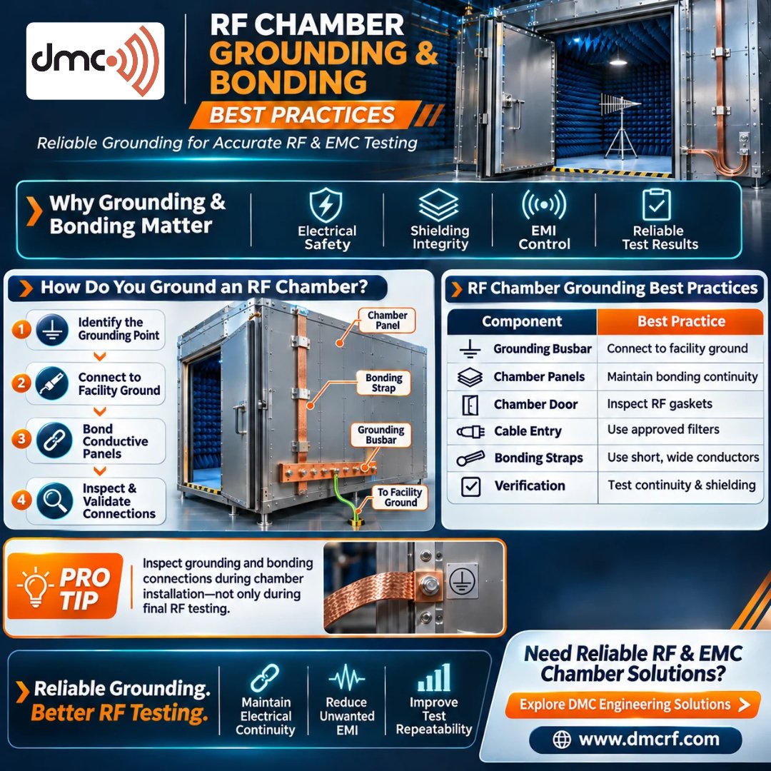
Grounding an RF chamber involves connecting its conductive structure to the facility’s engineered grounding system. The appropriate method depends on chamber construction, electrical design, operating frequency, safety standards, and manufacturer recommendations.
1. Establish a Dedicated Grounding Connection
Identify the chamber’s designated grounding terminal or busbar. Connect it to the facility grounding network according to the approved electrical design.
A qualified electrical engineer should determine the grounding arrangement and ensure compliance with local electrical regulations. Avoid improvised connections through plumbing or unrelated structural components.
2. Use Suitable Grounding Conductors
Select grounding conductors based on fault-current requirements, conductor length, installation conditions, and applicable electrical codes.
Copper conductors are commonly used because of their conductivity. For RF bonding applications, short and wide straps may offer lower inductance than long, narrow conductors.
However, RF bonding straps must never replace protective earth conductors required for electrical safety.
3. Maintain Electrical Continuity Across Chamber Panels
RF chambers may use steel panels, copper shielding, aluminum components, or modular conductive assemblies. All conductive sections forming the shielding boundary must maintain reliable electrical continuity.
Best practices include:
- Inspect panel-to-panel joints.
- Keep bonding surfaces clean and properly prepared.
- Follow specified fastening sequences and torque values.
- Use approved conductive gaskets and bonding hardware.
- Prevent paint or insulating materials from affecting bonding interfaces.
4. Bond RF Chamber Doors Properly
The chamber door is a critical part of the RF shielding enclosure. Conductive fingerstock, RF gaskets, and contact strips help maintain electrical continuity when the door is closed.
Inspect the door regularly for worn fingerstock, damaged RF gaskets, corrosion, uneven contact pressure, and loose hardware.
Damaged door bonding components can compromise shielding performance even when the rest of the chamber is properly installed.
5. Verify Cable Entry and Penetration Bonding
RF chambers contain cable penetrations, power feedthroughs, filters, and ventilation interfaces. These components must be integrated into the shielding design.
Use manufacturer-approved filtered feedthroughs and properly bonded penetration panels. Avoid routing unfiltered cables through improvised openings.
Cable shields should be terminated according to equipment design and applicable EMC requirements.
6. Separate Protective Earth and RF Reference Requirements
Protective earthing and RF reference bonding serve different purposes. Protective earthing reduces electric shock risks and provides a fault-current path, while RF bonding supports electromagnetic performance and signal integrity.
The grounding design must address both requirements without creating unintended ground loops.
Never disconnect protective earth conductors to troubleshoot RF noise.
7. Test Grounding and Bonding Connections
After installation, verify the grounding and bonding network using appropriate instruments and test procedures.
Testing may include protective earth continuity measurements, bonding resistance measurements, mechanical connection inspections, and RF shielding effectiveness measurements.
Acceptance limits must follow project specifications, applicable standards, and chamber manufacturer recommendations. A simple continuity check confirms a conductive path but does not necessarily prove acceptable RF shielding effectiveness.
RF Chamber Grounding and Bonding Best Practices
The following table summarizes essential installation and maintenance practices.
| Component | Best Practice | Engineering Benefit |
|---|---|---|
| Grounding busbar | Connect to the engineered facility grounding network | Supports grounding integrity |
| Grounding conductor | Select according to fault-current and code requirements | Reliable protective grounding |
| Shielding panels | Maintain clean and properly fastened bonding interfaces | Continuous shielding boundary |
| Chamber door | Inspect conductive fingerstock and RF gaskets | Maintains door shielding |
| Cable penetrations | Use approved filters and bonded feedthroughs | Controls unwanted EMI pathways |
| RF bonding straps | Use suitable short, wide conductors where appropriate | Reduces connection inductance |
| Equipment racks | Bond according to the grounding design | Improves equipment integration |
| Ventilation interfaces | Use properly designed RF shielding vents | Maintains shielding across openings |
| Grounding terminals | Inspect for corrosion, looseness, or damage | Reliable connections |
| Testing | Verify continuity and shielding performance | Confirms installation quality |
Common RF Chamber Grounding Mistakes to Avoid
Incorrect grounding and bonding can affect chamber safety, shielding integrity, and test reliability.
Using long grounding wires:
Long or loosely routed conductors can introduce additional impedance and inductance. Conductors should follow the engineered installation requirements.
Ignoring panel seams:
Loose fasteners, poor surface preparation, and damaged conductive interfaces can affect shielding continuity.
Overlooking door contact wear:
Repeated opening and closing can damage conductive fingerstock and RF gaskets. Regular inspection helps identify problems early.
Assuming ground continuity guarantees RF shielding:
A low-resistance electrical connection does not automatically guarantee the required shielding effectiveness across the operating frequency range.
Creating unplanned ground loops:
Multiple connections between equipment and grounding references may create unwanted current paths. Grounding topology should be designed by qualified engineers.
How Grounding and Bonding Affect RF Shielding Effectiveness
RF shielding effectiveness describes how well an enclosure reduces electromagnetic field transmission through its shielding boundary.
Grounding and bonding help maintain electrical continuity and control unwanted conductive paths. However, shielding performance also depends on material conductivity, panel thickness, joint design, operating frequency, door quality, cable penetrations, RF gasket condition, and installation quality.
At higher frequencies, small discontinuities and connection geometry can become increasingly important.
Therefore, RF chamber grounding should be treated as one part of a complete shielding system rather than a standalone solution.
RF Chamber Grounding Inspection and Maintenance Checklist
A regular inspection program helps identify bonding degradation before it affects chamber performance.
Recommended inspection activities include:
- Inspect grounding busbars and connection points.
- Check grounding conductors for damage or corrosion.
- Verify panel fastening and bonding interfaces.
- Examine door RF gaskets and conductive fingerstock.
- Inspect cable entry panels and filtered feedthroughs.
- Verify equipment rack bonding.
- Perform continuity tests at specified locations.
- Conduct shielding effectiveness testing when required.
- Document inspection findings and corrective actions.
- Maintain records of repairs and validation results.
Inspection frequency depends on chamber usage, operating environment, manufacturer guidance, and project quality requirements.
Pro Tip: Validate Bonding Before RF Chamber Acceptance
Do not wait until final RF testing to inspect grounding and bonding connections. Verify continuity during installation, particularly at panel joints, chamber doors, cable entry points, and grounding terminals.
Early verification helps identify installation problems before they become costly commissioning issues. Maintain records of grounding continuity, bonding measurements, and shielding effectiveness results for future maintenance and troubleshooting.
Why Choose DMC for RF Chamber Solutions?
Diamond Microwave Chambers (DMC) provides RF and EMC chamber solutions for demanding electromagnetic testing applications.
Reliable chamber performance requires careful integration of shielding panels, doors, RF absorbers, cable penetrations, ventilation systems, grounding interfaces, and test equipment.
DMC supports RF and EMC testing environments through chamber design and shielding solutions tailored to application requirements.
Organizations planning a new RF chamber, upgrading an existing enclosure, or evaluating chamber performance should include grounding and bonding in their overall technical specifications.
Conclusion
RF chamber grounding and bonding best practices are essential for safe electrical operation, reliable shielding integrity, and repeatable EMC and RF testing.
A properly designed grounding system, dependable bonding connections, well-maintained chamber doors, and correctly integrated cable penetrations support consistent chamber performance.
Grounding alone cannot guarantee RF shielding effectiveness. The complete chamber structure must be designed, installed, inspected, and validated according to relevant engineering specifications.
By following a structured grounding and bonding approach, RF testing facilities can improve installation quality, reduce unwanted interference, and maintain dependable testing environments.
Frequently Asked Questions
An RF chamber is grounded by connecting its designated grounding terminal or busbar to the facility’s engineered grounding network using appropriately sized conductors. The installation must meet electrical safety codes and chamber specifications.
Bonding maintains electrical continuity between conductive chamber components such as panels, doors, frames, and penetration interfaces. It helps preserve the integrity of the RF shielding boundary.
Grounding connects a system to a designated grounding reference or earthing network. Bonding connects conductive components together to maintain electrical continuity. Both serve different purposes in RF chamber design.
Proper grounding and bonding can support RF shielding performance, but shielding effectiveness also depends on materials, seams, doors, penetrations, frequency, and construction quality. It must be verified through appropriate testing.
Inspection frequency depends on chamber usage, environment, manufacturer recommendations, and quality requirements. Regular scheduled inspections should include grounding terminals, bonding interfaces, door contacts, and continuity measurements.