
Table of Contents
- What Is an Anechoic Chamber?
- How Does an Anechoic Chamber Absorb Radio Waves?
- The Science Behind RF Absorber Foam
- How DMC Supports RF and EMC Testing
Radio waves power modern communication, radar, and countless electronic devices. Yet unwanted reflections can distort measurements. That is why anechoic chambers absorb radio waves: they create a controlled space where RF, antenna, and electromagnetic compatibility (EMC) testing can be done reliably.
By combining RF absorbers, electromagnetic shielding, and a carefully engineered structure, an anechoic chamber recreates open-space conditions inside a laboratory. This guide explains how RF absorber foam works and why absorption matters for accurate electromagnetic measurements.
What Is an Anechoic Chamber?
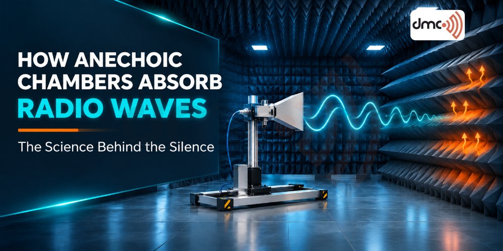
An anechoic chamber is an enclosed test facility built to minimize reflections of electromagnetic or sound waves. In RF and EMC applications, its interior is lined with Radiation Absorbent Material (RAM), typically pyramidal foam, ferrite tiles, or hybrid systems. RF-shielded walls keep external signals out, while the absorbers suppress internal reflections. Together with antennas, receivers, and a platform for the device under test (DUT), they let engineers evaluate antenna performance, emissions, and immunity.
How Does an Anechoic Chamber Absorb Radio Waves?
RF absorbers allow incoming radio waves to enter with minimal reflection and gradually dissipate their energy.
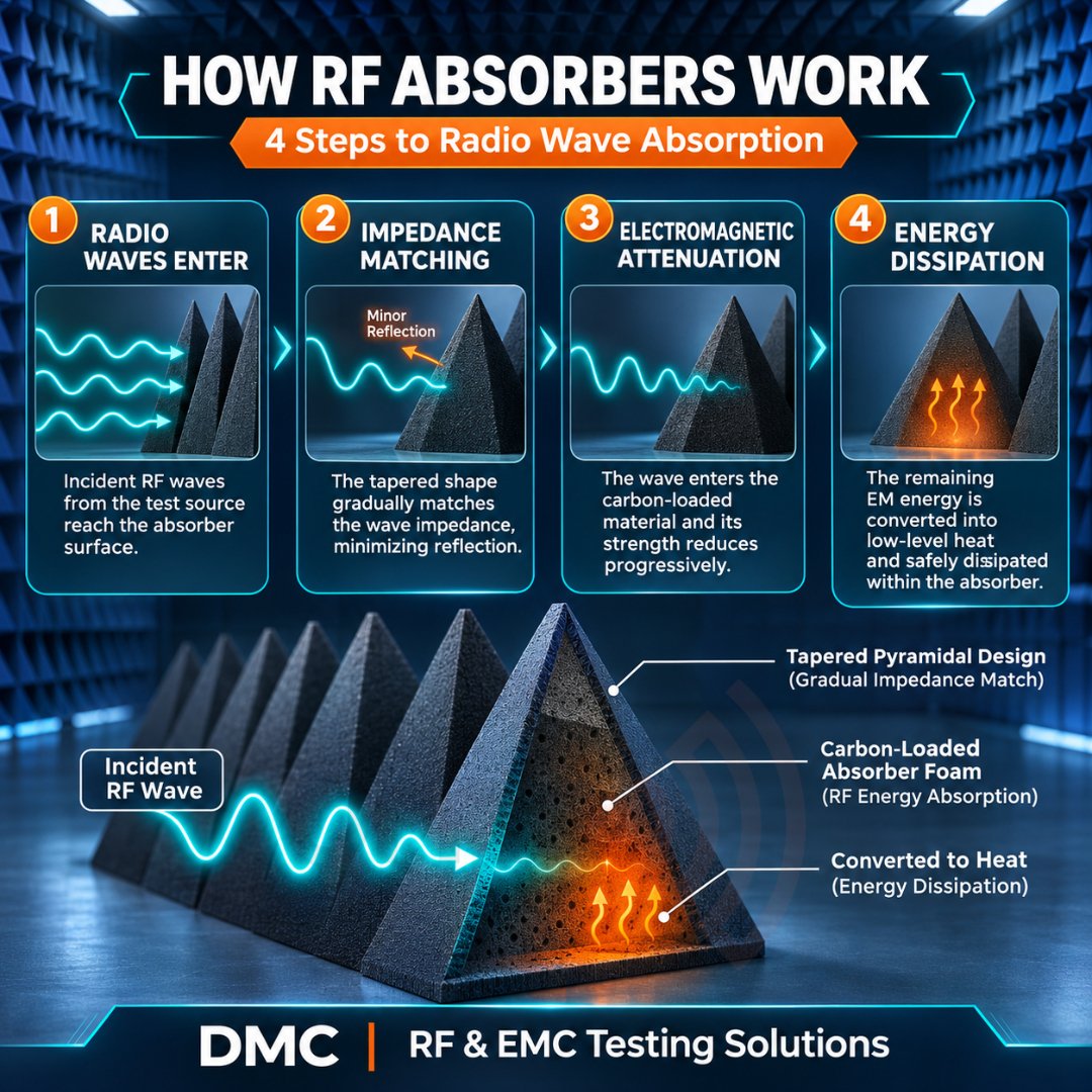
1. Waves Meet the Absorber
When a radio wave reaches an absorber, it meets a material with different electrical properties. The energy can be reflected, absorbed, or transmitted, depending on structure and backing. A good absorber keeps reflection low while absorbing as much energy as practical.
2. Impedance Matching Limits Reflection
Free space has an impedance of roughly 377 ohms for a plane wave. If an absorber surface differs sharply, part of the wave bounces back. Tapered, pyramidal absorbers solve this: the pointed shape exposes the wave to progressively more material as it travels deeper, so more energy enters and less reflects.
3. Lossy Materials Attenuate the Signal
Common absorber materials include carbon-loaded polyurethane foam and ferrite. The foam’s resistive particles interact with the electric field, while magnetic-loss materials act on the magnetic component. Energy is dissipated inside the absorber instead of returning to the test area.
4. Energy Becomes Heat
As the wave moves through the lossy structure, resistive, dielectric, and sometimes magnetic losses convert its energy into a small amount of heat, weakening it steadily with depth.
Geometry adds another layer. The inclined surfaces scatter waves toward other parts of the absorber rather than straight back at the test antenna, leaving a much weaker reflected signal.
The Science Behind RF Absorber Foam
RF absorber foam is among the most common materials in microwave and high-frequency chambers. Unlike acoustic foam, it is engineered specifically to interact with electromagnetic waves. Carbon-loaded polyurethane foam combines controlled conductivity, energy dissipation, and light weight, and its pyramidal or wedge shape supports frequency-dependent absorption.
Pyramids work because they ease the wave from air into the lossy material, cutting surface reflection and backscatter across a designed frequency range. Height matters: lower frequencies generally call for larger absorbers, though performance also depends on material design.
Types of RF Absorbers
Absorber choice depends on the chamber’s operating frequency, test requirements, and physical design.
| Absorber Type | Working Principle | Typical Application |
|---|---|---|
| Pyramidal foam | Gradual impedance transition | High-frequency RF and antenna testing |
| Ferrite tile | Magnetic and dielectric losses | Lower-frequency EMC testing |
| Hybrid | Ferrite plus foam | Broadband EMC chambers |
| Wedge | Tapered geometry limits scattering | Specialized RF environments |
| Flat | Material losses attenuate energy | Selected shielding and measurement uses |
RF Absorption vs. RF Shielding
Shielding stops unwanted signals from entering or leaving the enclosure, while absorption reduces reflections inside it. A reliable RF testing environment needs both.
| Feature | RF Shielding | RF Absorption |
|---|---|---|
| Purpose | Blocks external signals | Minimizes internal reflections |
| Materials | Copper and steel panels | Carbon foam, ferrite, hybrid RAM |
| Location | Walls and enclosure | Interior surfaces |
Why Radio Wave Absorption Matters in EMC Testing
EMC testing checks whether an electronic product works properly without causing unacceptable interference. Unwanted reflections can skew field strength, emissions, antenna patterns, and immunity results, so a well-designed chamber is essential.
- Antenna measurements: Pattern measurements depend on separating direct signals from reflected ones. Reflections cause constructive or destructive interference that distorts gain and directionality, and RF absorbers suppress them.
- Radiated emissions: A controlled chamber reduces measurement uncertainty caused by environmental reflections.
- Radiated immunity: Absorbers improve the uniformity and repeatability of the test environment, subject to chamber design and validation.
Wireless technologies: As 5G, mmWave, automotive radar, satellite, Wi-Fi, and IoT devices push frequencies higher, absorber geometry and chamber configuration matter
How DMC Supports RF and EMC Testing
DMC helps engineers build controlled electromagnetic measurement environments. Chamber performance depends on more than absorber material: dimensions, shielding effectiveness, absorber layout, antenna placement, test distance, and frequency range all play a part. Also weigh quiet-zone requirements, device size, and EMC compliance needs.
Pro Tip: Don’t choose RF absorber foam by height or appearance alone. Match it to the chamber’s lowest operating frequency, required reflectivity, and angle of incidence. Ferrite or hybrid absorbers suit lower frequencies, while pyramidal foam is common at higher ones. Always check the manufacturer’s reflectivity specifications and validate the finished chamber.
Conclusion
Anechoic chambers absorb radio waves through impedance matching, material losses, and carefully designed absorber geometry. RF absorber foam lets waves in with little reflection and dissipates their energy as heat, which is vital for reliable antenna characterization and EMC testing. Understanding this science helps engineers specify better chambers.
Frequently Asked Questions
RF absorbers reduce reflections through impedance matching and electromagnetic losses, dissipating the energy as heat.
Carbon-loaded polyurethane foam, ferrite tiles, and hybrid absorbers, chosen by frequency range and test requirements.
The shape gives a gradual transition from air to lossy material, reducing initial reflections.
Shielding blocks external signals; absorption minimizes internal reflections.
They provide a controlled, low-reflection environment for repeatable emissions, immunity, and antenna measurements.