
Table of Contents
- What is an Anechoic Chamber
- Core Elements of Designing Anechoic Chambers for Antenna Testing
- Important Design Parameters
- Common Challenges in Chamber Design
Modern wireless technologies demand exceptional antenna performance. Whether developing antennas for 5G, satellite communications, aerospace, automotive radar, IoT, or defense systems, accurate testing is essential before deployment. Designing Anechoic Chambers for Antenna Testing plays a vital role in eliminating unwanted reflections and electromagnetic interference, allowing engineers to evaluate antenna characteristics with high precision.
At Diamond Microwave Chambers Ltd, we design and manufacture advanced RF anechoic chambers that support reliable antenna measurements across research laboratories, production facilities, universities, defense organizations, and commercial testing centers. A properly designed chamber creates an environment that closely resembles free space, enabling engineers to obtain dependable and repeatable results.
This guide explains the key principles, design considerations, components, applications, and best practices involved in designing anechoic chambers for antenna testing.
What is an Anechoic Chamber?
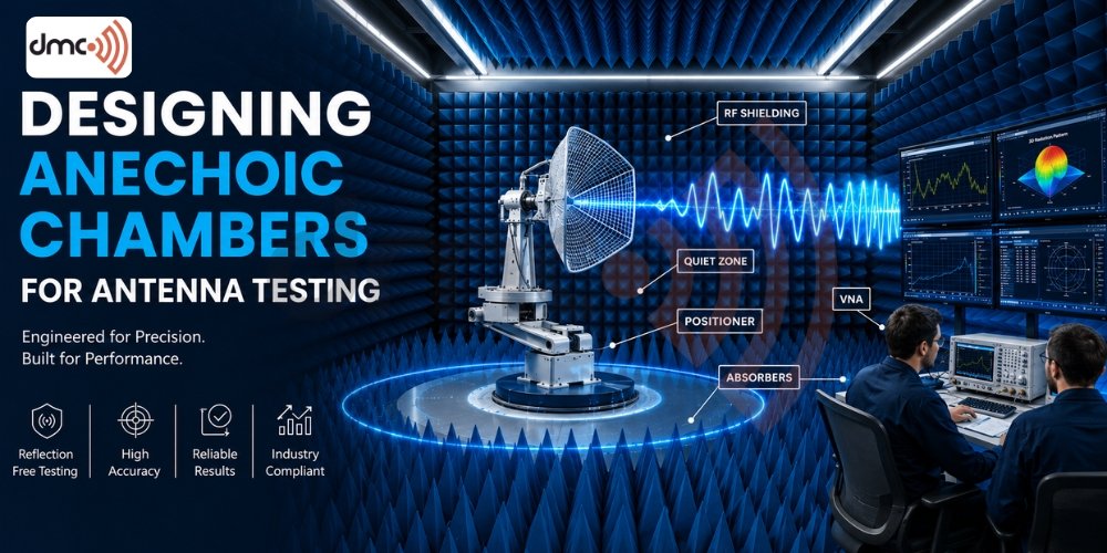
An anechoic chamber is a specially engineered room that absorbs electromagnetic waves instead of reflecting them. The chamber is enclosed within an RF shielded structure to block external electromagnetic signals while RF absorbers installed on the walls, ceiling, and often the floor minimize internal reflections.
The result is a controlled testing environment that simulates open-space conditions without environmental interference.
Engineers use these chambers to measure:
- Antenna gain
- Radiation patterns
- Beamwidth
- Polarization
- Efficiency
- Directivity
- Return loss
- Near-field and far-field performance
Without an anechoic chamber, reflected signals can distort measurements and reduce testing accuracy.
Why Proper Chamber Design Matters
Every antenna behaves differently depending on its frequency, size, application, and intended environment. Therefore, chamber design cannot follow a one-size-fits-all approach.
A well-designed chamber helps achieve:
- High measurement repeatability
- Reduced signal reflections
- Accurate radiation pattern measurements
- Improved OTA testing
- Compliance with international standards
- Reliable product validation
- Faster testing workflows
Poor chamber design can introduce unwanted reflections, standing waves, and inaccurate measurements that affect product development.
Core Elements of Designing Anechoic Chambers for Antenna Testing
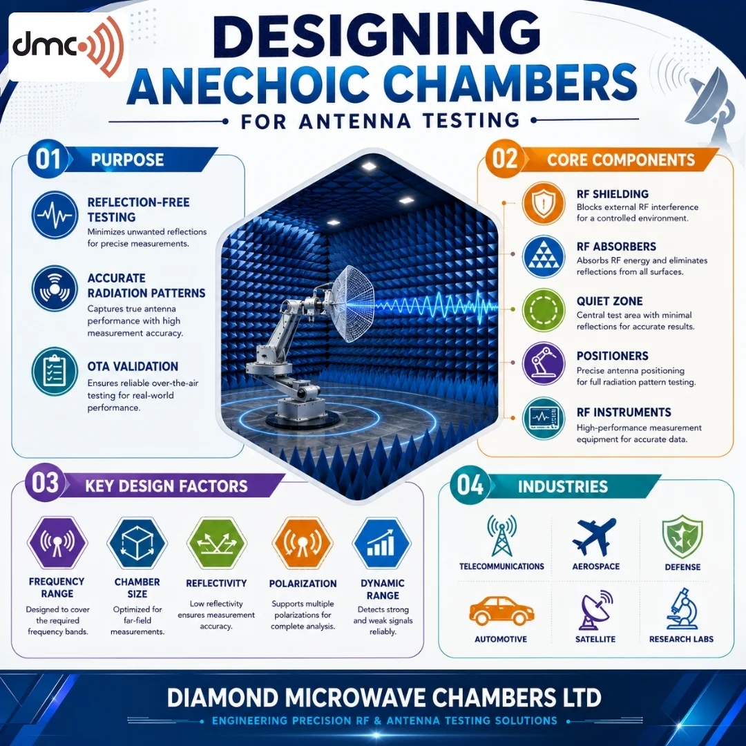
1. RF Shielding
The first requirement is preventing external electromagnetic signals from entering the chamber.
Shielding usually includes:
- Modular steel shielding panels
- Shielded RF doors
- Honeycomb air vents
- Filtered power lines
- Shielded cable entry panels
- Proper grounding systems
Shielding effectiveness typically exceeds 100 dB across specified frequency ranges depending on chamber requirements.
2. RF Absorbers
RF absorbers eliminate reflected energy inside the chamber.
Common absorber types include:
- Pyramidal absorbers
- Hybrid absorbers
- Ferrite tile absorbers
- Broadband microwave absorbers
Selection depends on:
- Frequency range
- Chamber size
- Testing application
- Required reflectivity
Lower frequencies generally require deeper absorbers because longer wavelengths are more difficult to absorb effectively.
3. Chamber Size
The chamber dimensions depend on:
- Antenna dimensions
- Measurement distance
- Operating frequency
- Far-field requirements
- Equipment placement
Insufficient chamber size may prevent accurate far-field measurements.
4. Quiet Zone Design
The quiet zone is the testing area where electromagnetic field conditions remain stable and free from unwanted reflections.
A properly designed quiet zone provides:
- Uniform field distribution
- Stable signal levels
- Low reflectivity
- High measurement confidence
This region is carefully optimized during chamber design.
5. Positioning Systems
Modern antenna testing requires automated positioning.
Typical positioners include:
- Azimuth rotation
- Elevation rotation
- Roll axis movement
- Multi-axis robotic positioners
Accurate positioning improves measurement repeatability and automation.
6. Measurement Equipment Integration
A complete chamber integrates multiple RF instruments.
Examples include:
- Vector Network Analyzer (VNA)
- Spectrum Analyzer
- Signal Generator
- Power Meter
- OTA Measurement Software
- Data Acquisition Systems
Proper equipment integration reduces testing complexity.
Types of Antenna Testing Chambers
| Chamber Type | Primary Application | Frequency Range |
|---|---|---|
| Full Anechoic Chamber | Precision Antenna Testing | Broad Frequency Range |
| Semi Anechoic Chamber | EMC and Antenna Measurements | Low to High Frequencies |
| Compact Range Chamber | Large Antenna Measurements | Microwave Frequencies |
| Near Field Chamber | Near-Field Scanning | High Precision Testing |
| OTA Chamber | Wireless Device Testing | Cellular, Wi-Fi, 5G, IoT |
Important Design Parameters
When designing an antenna chamber, engineers evaluate several technical parameters.
Frequency Range
Different absorber materials perform differently across frequency bands.
Examples include:
- VHF
- UHF
- L Band
- S Band
- C Band
- X Band
- Ku Band
- Ka Band
- Millimeter Wave
Reflectivity
Lower chamber reflectivity generally improves measurement accuracy.
Typical chamber specifications are selected according to testing objectives.
Dynamic Range
A higher dynamic range enables measurement of weak antenna signals while minimizing background noise.
Polarization Accuracy
The chamber should support:
- Vertical polarization
- Horizontal polarization
- Circular polarization
- Dual polarization
Positioning Accuracy
High-precision motors improve repeatability during antenna pattern measurements.
Industries Using Antenna Testing Chambers
Anechoic chambers support numerous industries.
These include:
- Telecommunications
- Aerospace
- Defense
- Automotive
- Satellite Communications
- Research Laboratories
- Universities
- Consumer Electronics
- Medical Electronics
- Semiconductor Industry
Each application requires chamber designs tailored to specific testing needs.
Common Challenges in Chamber Design
Engineers often face several challenges.
These include:
- Limited installation space
- Broad frequency coverage
- Low-frequency absorber performance
- Mechanical stability
- Shielding effectiveness
- Equipment integration
- HVAC noise reduction
- Future scalability
Proper planning helps minimize these challenges.
Pro Tip
Design the chamber based on your highest planned operating frequency—not just your current testing needs. As wireless technologies continue evolving toward higher frequencies, a future-ready chamber reduces upgrade costs and extends the facility’s operational lifespan.
Conclusion
Designing anechoic chambers for antenna testing requires a balance of RF engineering, shielding technology, absorber performance, automation, and measurement precision. A well-designed chamber provides the controlled environment needed for reliable antenna characterization across industries such as telecommunications, aerospace, automotive, and defense.
By selecting the appropriate chamber size, RF absorbers, shielding system, quiet zone, and positioning equipment, organizations can achieve accurate, repeatable, and standards-based antenna measurements. Diamond Microwave Chambers Ltd continues to support customers with customized chamber solutions engineered to meet evolving wireless testing requirements while maintaining high standards of quality and performance.
Frequently Asked Questions
It creates a controlled environment that minimizes reflections and external RF interference, enabling accurate antenna measurements.
RF absorbers reduce internal reflections, helping simulate free-space conditions for reliable antenna testing.
Telecommunications, aerospace, automotive, defense, satellite communications, research institutions, and electronics manufacturers commonly use them.
Chamber size depends on antenna dimensions, operating frequency, required measurement distance, and testing methodology.
Yes. A well-designed chamber can accommodate evolving technologies by considering broader frequency ranges and scalable system integration during the design phase.