
Table of Contents
- Specifying the Chamber Before Defining the Antenna
- Using the Wrong Test Method
- Underestimating Reflections and Scattering
Designing an antenna test range is an engineering choice that dictates the accuracy and repeatability of measurements, the equipment that can be used, and the potential of the laboratory in the long term. A range can appear to be adequate on a drawing, but can yield unreliable results if the frequency band, size of the antenna, the quiet zone, measurement distance, the degree of accuracy, and uncertainty of placement have not been specified. Diamond Microwave Chambers Ltd guides clients to design RF and antenna measurement facilities based on applications, as opposed to using a specification of a generic chamber.
Specifying the Chamber Before Defining the Antenna
Specifying the preferred chamber size prior to specifying the antenna to be tested is probably the most frequent mistake. The antenna’s aperture, dimensions, weight, and method of mounting, operating frequency, beam width, polarization, and measurement angles influence the far field range.
For example, a high gain large antenna may require a much greater separation in the far field compared to a small antenna. The commonly known far field relation is R ≥ 2D²/λ, in which R is the separation distance, D is the largest antenna dimension, and λ is the wavelength. NASA documentation also notes that for some measurements, there may be a need for greater separation distance, depending on the aperture phase and the uncertainty.
Better approach:
- Define the largest antenna first.
- Identify the lowest operating frequency.
- Record antenna weight and mounting requirements.
- Define required angular coverage.
- Establish the required measurement accuracy.
Choosing Frequency Range Too Narrow
If future products are not considered, the antenna laboratories may not be able to support the bands of future antennas, higher frequencies, phased arrays, automotive radars, satellite systems, and other evolving wireless technologies.
Frequency affects the performance of absorbers. It influences the size of the chamber, the design of source antennas, cables and connectors used, as well as the measurement and calibration instruments.
A practical specification should therefore identify:
- Minimum frequency
- Maximum frequency
- Continuous or discrete frequency bands
- Required measurement bandwidth
- Future frequency expansion
- Instrumentation compatibility
The goal is not simply to specify the widest possible frequency range. Over-specification can increase cost without providing useful measurement capability.
Ignoring Quiet-Zone Requirements
A chamber consisting of RF absorbers is not an accurate chamber. The quality of the quiet zone must offer the desired electromagnetic environment for the measurement.
The quality of the quiet zone is measured by amplitude, phase, reflections, and uniformity in the spatial domain. The NASA range specifications illustrate a quiet zone by establishing limits of amplitude and phase, thus demonstrating that the quiet-zone criteria are measurable and not arbitrary.
Common mistakes include:
- Specifying quiet-zone size without defining the antenna under test.
- Asking for extremely tight uniformity without a measurement justification.
- Ignoring phase requirements for applications where phase accuracy matters.
- Assuming absorber coverage alone guarantees adequate quiet-zone performance.
Using the Wrong Test Method
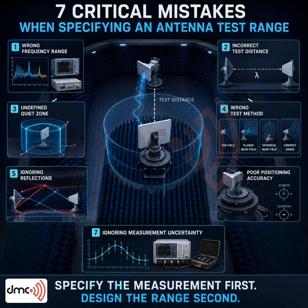
Not all antennas require traditional far-field testing. Depending on the dimension, frequency, and scope of the coverage required, engineers may consider far-field, planar near-field, cylindrical near-field, spherical near-field, or compact antenna test range approaches.
Near-field systems use mathematical transformation techniques to obtain far-field information. The IEEE outlines the importance of calibration, probe compensation, echo reduction, positioning, and uncertainty analysis in near-field measurements.
Choosing the wrong measurement method can incur unnecessary space, cost, or measurement restrictions.
Forgetting the Complete Measurement Geometry
The measurement geometry consists of the transmitter, antenna under test, positioner, absorber boundaries, cables, support structure, and chamber walls.
A range specification should clearly establish:
| Parameter | Why It Matters |
|---|---|
| Frequency range | Determines wavelength and RF hardware requirements |
| Maximum antenna size | Influences distance and quiet-zone requirements |
| Test distance | Supports appropriate far-field conditions |
| Quiet-zone size | Defines usable measurement volume |
| Angular coverage | Determines positioner and chamber requirements |
| Polarization | Affects source and measurement configuration |
| Dynamic range | Important for low-level pattern measurements |
| Position accuracy | Influences repeatability and angular results |
| Cable routing | Helps minimize unwanted coupling and movement |
| Calibration | Establishes measurement traceability and consistency |
Treating these items as independent results in integration issues.
Underestimating Reflections and Scattering
Unwanted reflections distort radiation patterns, gain, and sidelobe measurements. Chamber discontinuities, support structures, cables, doors, and other openings and paths for ventilation contribute to scattering.
IEEE technical notes state that chamber absorber configuration, ventilation, access paths, support structures, and discontinuities of chamber walls can affect the scattering of an anechoic chamber.
Therefore, the specification should address not just the type of chamber absorber material, but also the entire anechoic chamber.
Treating Positioning Accuracy as an Afterthought
Highly capable RF systems will not help resolve poor mechanical positioning. Poor mechanical positioning affects the final results due to factors such as Azimuth and elevation, polarization rotation, movement of the probes, and alignment of antennas.
When evaluating potential positioners, it is important to analyze the following specifications:
- Angular range
- Angular accuracy
- Repeatability
- Maximum payload
- Rotation speed
- Mechanical alignment
- Cable management
- Control-system integration
For automated antenna measurements, mechanical repeatability is most important, since small positioning discrepancies may become significant and complicate comparisons of measurement runs.
Ignoring Measurement Uncertainty
Uncertainty must be considered at the specification stage, and not after the chamber is constructed.
Some of the factors that affect uncertainty are cable losses, connector repeatability, receiver noise, calibration errors, positioning errors, reflections, alignment, dynamic range, and environmental effects. Both the IEEE and NASA material emphasize uncertainty as one of the more important aspects of antenna measurement.
Useful specifications indicate the required uncertainty or accuracy, and describe how the system will be checked.
Over-Specifying Everything
More performance is not better if the additional capability is unnecessary.
There are several examples where the performance requested may significantly increase the cost and complexity of the project, such as very large quiet zones, extremely low amplitude variation, ultra-wide frequency coverage, or extremely high positioning precision.
A good specification should connect each major performance criterion to a relevant measurement requirement.
Forgetting Future Expansion
Antenna laboratories often remain in service for many years. Designing just for the first project may make future upgrades much more difficult.
Consider:
- Larger antennas
- New frequency bands
- Additional positioners
- Automated measurement software
- Higher dynamic-range receivers
- Phased-array testing
- OTA requirements
- Additional calibration equipment
NASA has many antenna ranges with various sizes of antennas and frequencies illustrating why architecture needs to match the range and measurement application.
Pro Tip
Do not front load an antenna test range specification with chamber dimensions. Antenna test range specifications should begin with measurements requirements. Describe the antennas and frequency bands, accuracy, quiet-zone volume, angular coverage, test method, and future requirements then design the chamber and measurement system around those requirements.
Conclusion
The most expensive mistakes for an antenna test range occur before the first shovel is picked up and involve selecting a chamber without considering the quiet zone, replicating specs from other labs, and selecting a chamber based on the only available space. Limitations from these oversights often result in expensive and prolonged modifications.
A good antenna test range is a complete measurement system and not simply an absorbing room. Frequency, antenna size, test distance, quiet zone performance, mechanical positioners, RF instruments, calibration and measurement uncertainty need to work as an integrated system.
Diamond Microwave Chambers Ltd offers engineered solutions based on customer RF and antenna measurement requirements. DMC has the experience to design high confidence measurement systems that that enhance measurement capability in current domain and provide future flexibility.
Frequently Asked Questions
An antenna test range is a controlled measurement environment used to characterize antenna performance such as radiation patterns, gain, directivity, and polarization while minimizing unwanted environmental effects.
For conventional far-field testing, a commonly used criterion is approximately R ≥ 2D²/λ, where D represents the relevant maximum antenna dimension and λ is wavelength. Specific applications may require additional margin or a different measurement approach.
The quiet zone is the usable measurement region where the electromagnetic field meets specified amplitude, phase, and reflection requirements. Its required size depends on the antenna and measurement application.
No. Far-field, planar near-field, cylindrical near-field, spherical near-field, and compact antenna test range methods can each be appropriate depending on antenna size, frequency, available space, and measurement objectives.
Measurement uncertainty helps quantify how factors such as calibration, positioning, cables, reflections, receiver performance, and alignment can influence reported antenna results.