
Table of Contents
- How do microwave absorbers work?
- Types of Microwave Absorbers and Their Working Mechanisms
- Why Microwave Absorbers Are Important in Anechoic Chambers
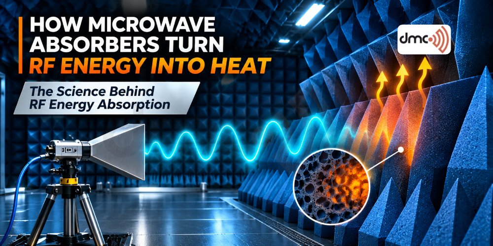
Microwave absorbers play a crucial role in modern RF and EMC testing by reducing unwanted electromagnetic reflections. In anechoic chambers, microwave absorbers help create controlled testing environments where antennas, wireless devices, radar systems, and electronic equipment can be evaluated accurately. Understanding how microwave absorbers turn RF energy into heat is essential for engineers designing reliable electromagnetic testing facilities.
These specialized materials interact with electromagnetic waves and convert a portion of the incoming RF energy into thermal energy. Instead of allowing radio waves to reflect strongly from chamber walls, microwave absorbers dissipate electromagnetic energy, reducing interference and improving measurement accuracy.
How do microwave absorbers work?
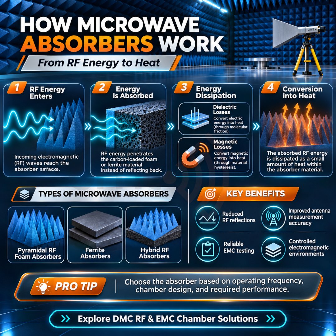
Microwave absorbers work by allowing electromagnetic waves to enter an absorbing material, where the RF energy is gradually dissipated as heat. This process involves three primary mechanisms: impedance matching, electromagnetic energy penetration, and dielectric or magnetic losses.
When an electromagnetic wave reaches an absorber, a portion of the energy may be reflected at the surface. The remaining energy enters the material and interacts with its internal structure. Through electrical and magnetic losses, the material converts the electromagnetic energy into thermal energy.
The effectiveness of this process depends on the absorber’s composition, geometry, thickness, operating frequency, and electrical properties.
1. Impedance Matching
Impedance matching is one of the most important factors in microwave absorption.
When the impedance of an absorber’s surface is close to the impedance of free space, electromagnetic waves can enter the material with less reflection. This allows more RF energy to penetrate the absorber rather than bounce back into the chamber.
Pyramidal RF absorbers are commonly designed with tapered structures that gradually transition from air to the absorbing material. This geometry helps reduce reflections across a specified frequency range.
2. Electromagnetic Wave Penetration
After entering the absorber, electromagnetic waves travel through its structure. The wave’s amplitude gradually decreases as energy is dissipated within the material.
The absorber’s thickness and internal properties determine how deeply electromagnetic energy can penetrate. Thicker absorbers are often required for lower-frequency applications, while appropriately designed thinner materials may perform effectively at higher frequencies.
3. Dielectric Loss Mechanism
Dielectric loss occurs when an electric field interacts with the material’s molecular or microscopic structure.
As the alternating electric field changes direction at microwave frequencies, polarization mechanisms within the material respond to it. This response is not perfectly instantaneous, resulting in energy dissipation.
Carbon-loaded foam and other lossy dielectric materials are widely used in RF absorbers because they can dissipate electromagnetic energy through dielectric losses.
4. Magnetic Loss Mechanism
Magnetic losses occur when the magnetic component of an electromagnetic wave interacts with magnetic materials.
Ferrite absorbers are an important example. Their magnetic properties enable electromagnetic energy to be dissipated through mechanisms such as magnetic resonance and domain-related losses.
Ferrite tiles are commonly used in EMC chambers, especially where low-frequency absorption is required. Hybrid absorber configurations combine ferrite materials with foam absorbers to provide broader frequency coverage.
5. Conversion of RF Energy into Heat
The energy absorbed by the material is ultimately converted into thermal energy.
At a microscopic level, electromagnetic fields cause electrical polarization and magnetic responses within the material. These responses involve energy losses, which appear as small increases in material temperature.
Under normal RF chamber operating conditions, the temperature rise may be very small. The primary objective is not to generate noticeable heat but to suppress electromagnetic reflections.
Types of Microwave Absorbers and Their Working Mechanisms
Different microwave absorber materials are designed for specific frequency ranges and testing requirements.
| Absorber Type | Material | Working Mechanism | Typical Application |
|---|---|---|---|
| Pyramidal Absorbers | Carbon-loaded foam | Dielectric losses and tapered impedance transition | Antenna measurement chambers |
| Wedge Absorbers | RF absorbing foam | Gradual impedance transition and energy dissipation | EMC testing |
| Ferrite Tiles | Magnetic ceramic | Magnetic losses | Low-frequency EMC chambers |
| Hybrid Absorbers | Ferrite and foam | Combined magnetic and dielectric losses | Broadband EMC chambers |
| Flat Absorbers | Lossy foam or composites | Dielectric energy dissipation | Compact RF environments |
Why Microwave Absorbers Are Important in Anechoic Chambers
Microwave absorbers are essential for controlling reflections inside anechoic chambers. Without effective absorption, reflected electromagnetic waves can interfere with the direct signal from the antenna under test.
This can result in inaccurate radiation patterns, incorrect gain measurements, unstable results, and unwanted multipath interference.
High-performance RF absorbers help engineers achieve:
- Reduced electromagnetic reflections.
- Improved antenna measurement accuracy.
- Better repeatability of RF testing.
- Controlled electromagnetic environments.
- Reliable EMC and OTA testing conditions.
The absorber design must be selected based on operating frequency, chamber dimensions, required reflectivity, and the test standard.
Factors Affecting Microwave Absorption Performance
Several parameters influence how effectively an absorber converts RF energy into heat.
Operating Frequency: Absorber performance varies with frequency. A material effective at one frequency may provide limited absorption at another.
Material Thickness: Thickness influences penetration depth and energy dissipation. Lower-frequency absorption often requires greater thickness.
Material Composition: Carbon loading, magnetic components, dielectric properties, and material density affect absorption characteristics.
Geometry: Pyramidal and wedge structures help reduce reflections by creating gradual transitions.
Installation Quality: Gaps, damaged absorber tips, incorrect placement, and exposed conductive surfaces can increase reflections.
Pro Tip: Select Absorbers Based on Frequency
Do not select microwave absorbers based only on their physical appearance or thickness. Review the frequency range, reflectivity performance, material specifications, and chamber requirements. For broadband applications, hybrid absorber solutions may provide better performance across multiple frequency bands.
Conclusion
Microwave absorbers convert RF energy into heat through electromagnetic interactions involving dielectric and magnetic losses. Impedance matching helps electromagnetic waves enter the material, while its internal structure gradually dissipates the energy.
In RF and EMC testing, these materials are fundamental to minimizing reflections and maintaining accurate measurements. Selecting the correct absorber design, material, and frequency range is essential for building reliable anechoic chambers.
Diamond Microwave Chambers (DMC) provides RF and EMC chamber solutions engineered for demanding electromagnetic testing applications.
Frequently Asked Questions
Microwave absorbers convert RF energy into heat through dielectric and magnetic losses. Electromagnetic waves penetrate the absorber material, where interactions with its electrical and magnetic properties dissipate the energy as thermal energy.
Common materials include carbon-loaded polyurethane foam, expanded polypropylene (EPP), ferrite tiles, and specialized lossy composites. Material selection depends on the required frequency range and absorption performance.
Microwave absorbers reduce unwanted electromagnetic reflections from chamber walls, ceilings, and floors. This creates a controlled testing environment for accurate antenna measurements, EMC testing, and OTA testing.
Dielectric absorption occurs through losses associated with electric field interactions in a material. Magnetic absorption occurs through interactions between electromagnetic magnetic fields and magnetic materials, such as ferrite.
Not always. Thickness can improve absorption, particularly at lower frequencies, but performance also depends on material properties, absorber geometry, impedance matching, and the operating frequency.