
Table of Contents
- What Are Drone Radar and Anti-Collision Antennas?
- Which Parameters Should You Measure?
- What Test Environment Do You Need?
- Common Testing Mistakes
To test drone radar and anti-collision antennas, measure return loss (S11) with a calibrated VNA. Then capture radiation patterns, gain, sidelobes, and polarization in an anechoic chamber at a valid far-field distance. Finally, repeat the checks with the antenna installed on the drone, including its radome and airframe.
What Are Drone Radar and Anti-Collision Antennas?
Drone radar antennas send and receive RF signals to detect obstacles, measure distance, and track relative speed. Most anti-collision systems use compact patch-array antennas inside FMCW radar modules. Common bands are 24 GHz, 60 GHz, and 77–81 GHz.
The antenna pattern decides what the radar can “see”. A distorted beam or weak gain can cause missed obstacles, false alarms, and wrong angle estimates. That is why antenna testing comes before any flight validation.
Which Parameters Should You Measure?
| Parameter | Why It Matters | Test Method | What to Check |
|---|---|---|---|
| Return loss (S11) / VSWR | Shows how much power reaches the radiator | VNA, free-space | S11 ≤ −10 dB (VSWR ≤ 2:1) across the band |
| Radiation pattern | Defines the field of view | Azimuth/elevation cuts in a chamber | Beamwidth matches design spec |
| Gain | Sets detection range | Gain-transfer with a standard gain horn | Matches datasheet tolerance |
| Sidelobe level | Controls clutter and false targets | Pattern cuts | Below design limit |
| Polarization / cross-pol | Keeps target returns consistent | Rotating linear source | Cross-pol well below co-pol |
| Tx–Rx isolation | Prevents receiver desensitization | 2-port VNA (S21) | Low coupling per spec |
| Phase/amplitude balance (arrays) | Drives angle-of-arrival accuracy | Per-channel measurement | Within design tolerance |
What Test Environment Do You Need?
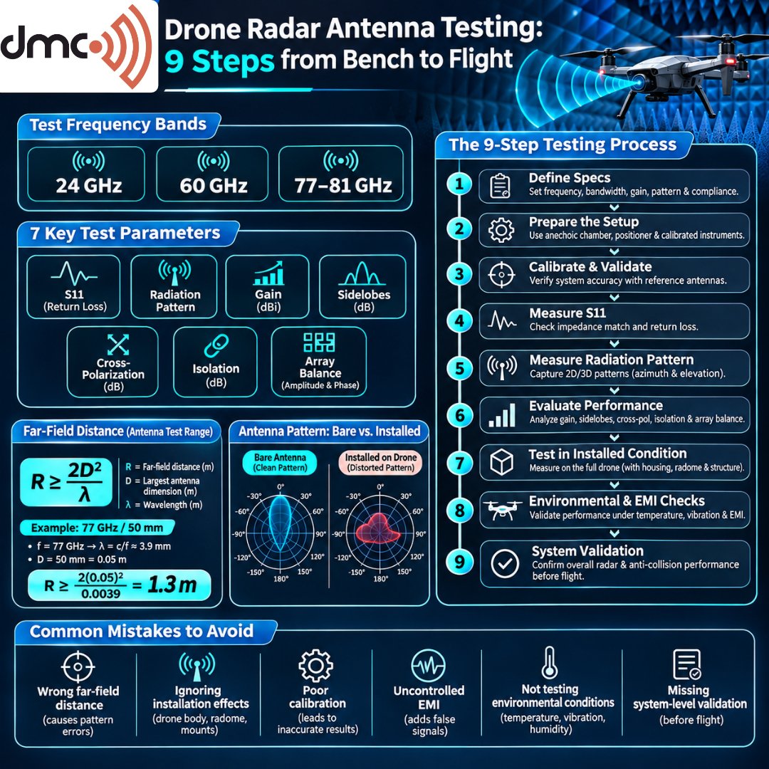
- Anechoic chambers: Absorber-lined walls keep reflections out of the quiet zone. Reflections at mmWave frequencies can distort sidelobe readings.
- Far-field distance: Use R ≥ 2D²/λ. For a 50 mm aperture at 77 GHz (λ ≈ 3.9 mm), the distance is about 1.3 m.
- Positioner: A precise azimuth-over-elevation positioner holds the antenna’s phase center at the rotation axis.
- Instruments: A VNA with mmWave extenders, a standard gain horn, a low-loss cable set, and a calibration kit.
- Near-field option: Planar near-field scanning suits compact arrays. Software transforms the near-field data into far-field patterns.
Step-by-Step Testing Process
1. Define the test plan. Record the frequency band, aperture size, connector type, and target specs.
2. Calibrate the VNA. Calibrate at the exact reference plane of the antenna connector. At mmWave, cable movement can change phase.
3. Measure S11 and VSWR. Run a sweep across the full band in free space, away from metal objects.
4. Align the antenna. Mount it on the positioner and align boresight with the probe or source antenna.
5. Capture co-pol and cross-pol patterns. Record azimuth and elevation cuts at the low, center, and high band frequencies.
6. Measure gain. Compare against a standard gain horn of known gain (gain-transfer method).
7. Test array channels. For multi-channel radar, check phase and amplitude balance on each Tx/Rx path.
8. Test installed performance. Fit the radome, mounting plate, and nearby frame parts, then repeat the pattern cuts.
9. Validate at system level. Place a corner reflector at known distances to confirm range and detection. A 4 GHz sweep gives about 3.75 cm range resolution (c/2B).
Pro Tip: Always run one set of tests with the radome, mounting bracket, and carbon-fiber or metal frame parts in place. A bare antenna can show a clean pattern, while the installed one shows beam squint, ripples, and gain loss. Comparing “bare” and “installed” patterns shows exactly which part causes the distortion.
Common Testing Mistakes
- Measuring inside the near-field zone and reading the pattern as far-field
- Skipping calibration after moving or flexing cables
- Testing only at center frequency and missing band-edge issues
- Ignoring cross-polarization
- Leaving absorber gaps or metal fixtures in the beam path
- Treating a good S11 as proof of a good pattern
Testing drone radar and anti-collision antennas means checking impedance, pattern, gain, polarization, and installed performance across the full band. A controlled chamber and a correct measurement setup give results you can trust before flight trials. DMC provides antenna measurement systems and anechoic chamber solutions for this kind of testing.
Frequently Asked Questions
Calibrate a VNA and measure S11 across the band. Then measure radiation patterns, gain, and polarization in an anechoic chamber at far-field distance. Finish by repeating the tests with the radome and airframe in place.
Most use 24 GHz, 60 GHz, or 77–81 GHz. Higher bands give finer range resolution and smaller antennas. Lower bands usually give longer range for the same power.
The absorbers remove reflections that distort pattern, sidelobe, and gain readings. This matters at mmWave frequencies, where small reflections change results.
Use R ≥ 2D²/λ, where D is the largest antenna dimension and λ is the wavelength. A 50 mm aperture at 77 GHz needs about 1.3 m.
Yes. Planar near-field scanning measures close to the antenna and converts the data to far-field patterns. It suits compact arrays. S11 can also be checked on the bench, but patterns still need a controlled environment.