
Table of Contents
- Why GNSS Antennas Need Special Attention
- The Building Blocks of GNSS Antenna Characterization
- Step-by-Step: How the Evaluation Actually Works
- Chamber Testing vs Field Testing
- Common Mistakes Teams Make
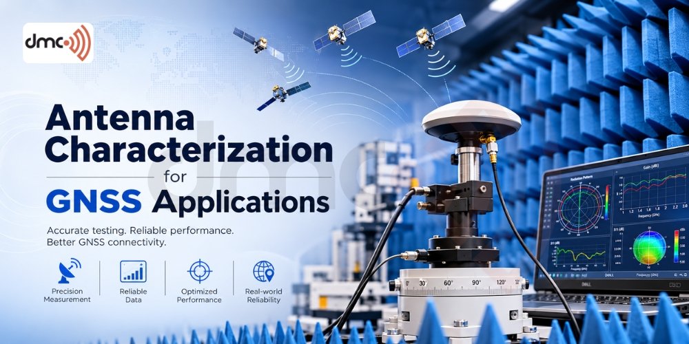
Antenna characterization for Global Navigation Satellite Systems (GNSS antennas) is the precise measurement of an antenna’s electrical and physical traits—such as signal gain, polarization, and phase center stability—to ensure accurate and reliable satellite positioning.
Why GNSS Antennas Need Special Attention
A few months back, one of our clients brought in a batch of patch antennas meant for a fleet-tracking device. On paper, the specs looked fine. Out in the field, the units kept losing lock near buildings and under tree cover. The antenna wasn’t “broken” — it just hadn’t been characterized properly for how GNSS signals actually behave.
GNSS signals arrive from satellites low on the horizon just as often as from directly overhead, they’re weak by the time they reach the ground, and they’re right-hand circularly polarized (RHCP). An antenna that isn’t tested against these realities can pass a basic gain check and still fail in the real world. That’s the gap antenna characterization is meant to close.
At Diamond Microwave Chambers Ltd, this is a large part of what we do day to day — putting GNSS antennas through controlled, repeatable tests so engineers know exactly what they’re deploying before it ships.
The Building Blocks of GNSS Antenna Characterization
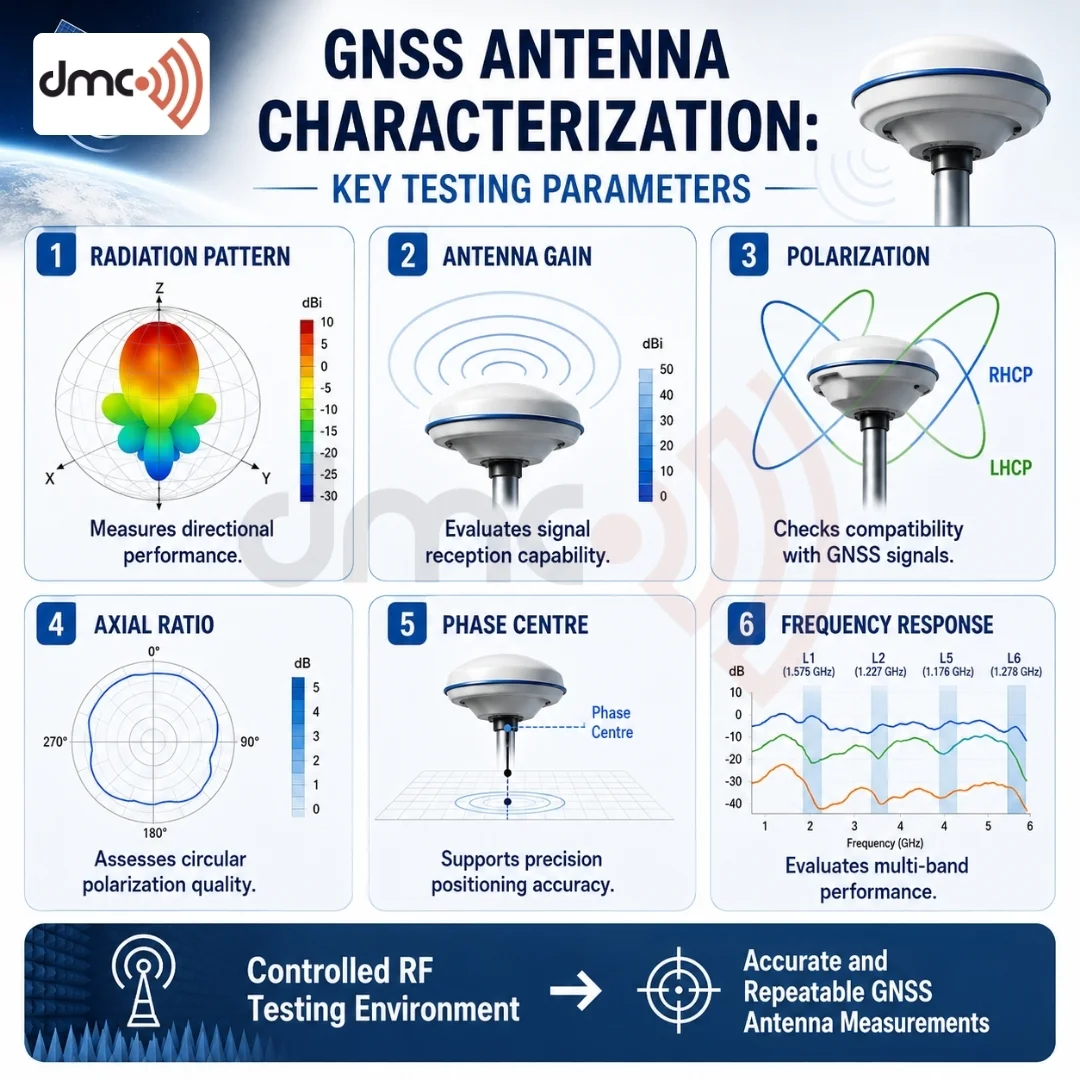
There isn’t one single measurement that tells you an antenna is “good.” It’s a set of parameters that, together, paint the full picture:
- Radiation pattern — how gain varies across azimuth and elevation, especially at low elevation angles near the horizon
- Axial ratio — how close the antenna comes to pure circular polarization; a poor axial ratio means signal loss and higher multipath sensitivity
- Phase center variation (PCV) — how the electrical center of the antenna shifts with angle of arrival, which matters a lot for survey-grade and RTK applications
- Gain-to-noise-temperature (G/T) for active antennas with built-in LNAs
- Group delay variation — inconsistent delay across the band can introduce timing errors, which is a real problem for GNSS since the whole system runs on precise timing
- Return loss / VSWR — confirms the antenna is actually radiating the power it’s given rather than reflecting it back
Each of these answers a different question, and skipping one usually means the failure shows up later — in the field, not in the lab.
Step-by-Step: How the Evaluation Actually Works
- Mount the antenna on a low-reflectivity positioner inside an anechoic chambers, oriented so the boresight faces the source antenna.
- Sweep frequency and angle across the GNSS bands of interest — L1, L2, L5 for GPS, or the equivalent bands for GLONASS, Galileo, and NavIC depending on the target market.
- Record co-polar and cross-polar patterns at each elevation cut, since axial ratio is calculated directly from this data.
- Extract the phase center by comparing phase data across multiple angles and fitting it to a reference point.
- Repeat with the antenna in its actual housing (radome, ground plane, cabling) — a bare antenna and an integrated antenna rarely measure the same.
- Compile the dataset into pattern plots, axial ratio curves, and a summary table for the design team.
That last step matters more than it sounds. Raw measurement data is only useful once it’s turned into something an RF engineer can act on quickly.
Chamber Testing vs Field Testing
| Parameter | Anechoic Chamber Testing | Open-Field Testing |
|---|---|---|
| Repeatability | High — controlled RF environment | Low — weather, terrain, and multipath vary |
| Multipath control | Reflections absorbed by chamber lining | Present and often unpredictable |
| Time required | Hours for a full pattern sweep | Days, sometimes weeks for statistically useful data |
| Regulatory acceptance | Standard for certification data | Used mainly for supplementary validation |
| Cost per test cycle | Higher upfront (chamber access) | Lower per session, but harder to reproduce results |
Neither approach replaces the other. Chamber data gives you the clean baseline; field testing tells you how the antenna behaves once real-world clutter gets involved.
Pro Tip: If your GNSS antenna will sit near other RF components — a cellular modem, Wi-Fi module, or metal chassis — characterize it in that exact configuration, not standalone. De-tuning from nearby conductive parts is one of the most common reasons a “perfect” antenna underperforms once it’s installed in the final product.
Common Mistakes Teams Make
- Testing only at boresight and assuming low-elevation performance will follow the same curve
- Ignoring axial ratio degradation at wide angles, which quietly increases multipath error
- Ground plane size overlooked — GNSS patch antennas are especially sensitive to this
- Treating an active antenna’s LNA gain as a substitute for good passive antenna design
- Skipping phase center testing because it’s assumed “close enough” for the application — these backfires quickly in survey and precision-agriculture use cases
Frequently Asked Questions
L1 (1575.42 MHz) is the baseline for most consumer and automotive GNSS work. Applications needing better accuracy or multi-constellation support also test L2 and L5, along with the equivalent Galileo and GLONASS bands.
GNSS signals are right-hand circularly polarized. A high axial ratio means the antenna doesn’t respond to that polarization efficiently, which shows up as weaker signal lock and more sensitivity to reflected (multipath) signals.
It can be approximated in an open field, but results won’t be repeatable or free of reflections. For certification-grade or design-validation data, a chamber is the practical standard.
If the electrical phase center shifts as the satellite geometry changes, it introduces small positioning errors. For most consumer devices this is negligible; for survey-grade or RTK systems, it can matter significantly.
Yes. A radome, cable routing, or nearby ground plane can shift resonant frequency and radiation pattern. Antennas should always be tested in their final mechanical configuration, not as a bare element.