

Table of Contents
- What is Planar Near-Field Measurement?
- Planar Near-Field vs Far-Field Measurement
- Step-by-Step Process
- Although planar near-field measurement technique is very effective, it does present certain difficulties such as:
Planar near-field measurement is among the most commonly employed approaches for measuring the performance of antennas as well as electromagnetic compatibility (EMC) tests. This approach facilitates the determination of the radiation pattern in the far field of antennas through the measurement of the electromagnetic field in the near field region.
The method is extremely useful in the lab environment because far field measurements cannot be conveniently made owing to spatial limitations. However, through mathematics, it is possible to achieve accurate far-field measurements from near-field readings.
In this article, you will find everything that is necessary to conduct a planar near-field measurement.
What is Planar Near-Field Measurement?
The process of planar near-field measurement refers to scanning the electromagnetic field at a plane location near the antenna under test (AUT) and processing the data through Fourier transform algorithms to deduce the radiating properties at a far-field distance.
The applications for this type of measurement include:
- Antenna design validation
- EMC testing
- RF system performance Analysis
- Radar and satellite systems
Key Equipment Required
Prior to conducting the measurements, please make sure that the following pieces of equipment are ready to use:
- Near-field scanning probe (planar scanning)
- Probe antenna (E-field/H-field probe)
- Vector network analyzer (VNA)
- Positioning system (XY-scanner)
- Measurement software
- High-frequency RF cables
- An absorber-lined chamber (anechoic chamber is preferable)
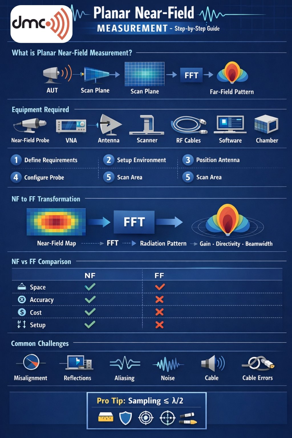
Planar Near-Field vs Far-Field Measurement
| Feature | Planar Near-Field Measurement | Far-Field Measurement |
|---|---|---|
| Space Requirement | Compact | Large area required |
| Measurement Distance | Close to antenna | Far from antenna |
| Accuracy | High (with transformation) | Direct measurement |
| Cost | Moderate | High |
| Environment | Controlled lab setup | Open/large chamber |
| Data Processing Required | Yes | Minimal |
Step-by-Step Process
1. Defining Measurement Requirements
Identify the parameters that need measurement:
- Range of frequencies
- Size of the antenna
- Radiation pattern
- Polarization
The information helps set up the environment and prevents mistakes during measurements.
2. Creating Measurement Conditions
Place the antenna in the anechoic chamber. This will avoid interference from other sources.
This step involves:
- Grounding
- Absence of cable movement
- The installation of the antenna
3. Preparing the AUT
Place the antenna on a stationary support structure. The antenna must not move during the process.
Considerations:
- The importance of antenna alignment
- The definition of the reference axis
- Antenna orientation
4. Preparing the Scanner and the Antenna
Connect the probe antenna to the planar scanner assembly.
This stage involves:
- Selecting the appropriate probe antenna
- Calibrating the probe antenna
- Defining the distance between scanning points in the plane
5. Determination of the Scanning Area
The scanning area must include all antenna aperture areas.
Considerations:
- Scanning beyond the aperture
- Distance between points in the scanning area
- Number of samples in the scanning area
6. Measurement System Calibration
Calibration provides accurate measurement results.
This step includes:
- VNA calibration
- Correcting the probe antenna
- Loss accounting
7. Perform the Near-Field Scan
Carry out the automated scanning procedure:
- Sweep probe through X-Y plane
- Measure amplitude and phase values
- Make sure there are no disturbances
The duration can vary based on resolution and area scanned.
8. Data Collection and Verification
Once the scan is complete:
- Check accuracy of gathered data
- Look for any unusual readings
- Conduct scan again if needed
9. Convert Near-Field to Far-Field
Apply computer programs (Fourier Transform) to transform near-field readings to far-field images.
Results will be:
- Radiation pattern
- Gain
- Directivity
- Beamwidth
10. Evaluate Results
Lastly, analyze the outcome:
- Compare against intended design specifications
- Note any problems with performance
- Tweak antenna design if required
Common Challenges
While planar near-field measurement is powerful, it comes with challenges:
- Alignment errors
- Probe positioning inaccuracies
- Environmental reflections
- Insufficient sampling resolution
- Cable interference
Addressing these issues ensures reliable measurements.
Although planar near-field measurement technique is very effective, it does present certain difficulties such as:
- Misalignment errors
- Imprecise probe location
- Reflections from the environment
- Low sampling rate
- Interference from cables
To overcome such obstacles would be a guarantee of getting correct measurements.
Advantages of Planar Near-Field Measurement
- Compact test setup
- High level of precision when properly configured
- Adaptability for large antennas
- Consistency of results
- Detailed field investigation capability
Tip of the Day
Make sure that the scanning plane is larger than one-half wavelength relative to the antenna size.
Best Practices
- Use high-quality RF cables
- Maintain a stable testing environment
- Avoid placing metal objects near the measurement setup
- Perform regular calibration of equipment
- Verify results using simulation software
Planar near-field measurement is one of the most crucial methods used in antenna testing and EMC validation. By following a well-defined methodology, engineers can achieve highly accurate results without requiring large far-field ranges.
Using this method correctly will allow you to gain insights into how your antenna performs.
Frequently Asked Questions
It is used to measure antenna radiation characteristics in a compact space and convert them into far-field results.
Using mathematical transformations such as Fourier Transform (FFT).
Typically, within the reactive or radiating near-field region, depending on antenna size and frequency.
To eliminate reflections and external electromagnetic interference for accurate measurements.
Probe alignment, calibration, environmental noise, and sampling resolution all impact accuracy.