
Table of Contents
- What Is Far-Field Distance?
- Why This Matters for Chamber Design
- Frequency and Antenna Size: The Two Biggest Variables
- Compact Range Solutions When Space Is Limited
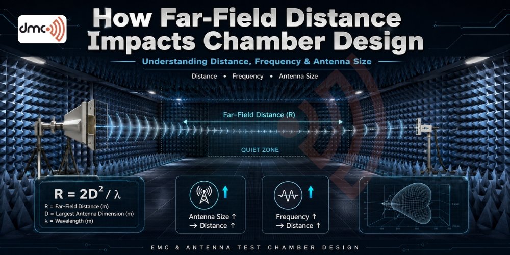
Anyone specifying an antenna test chamber eventually runs into one deceptively simple question: how far away does the antenna need to be from the device under test for the measurement to actually mean something? The answer is not a fixed number. It depends on frequency, antenna size, and the physics of how electromagnetic waves behave as they travel outward from a source. Getting this calculation wrong at the design stage leads to chambers that are either oversized and expensive or undersized and unreliable. This is why far-field distance sits at the center of every serious chamber design conversation, whether the facility is being built for antenna compliance testing, antenna pattern measurement, or radar cross-section work.
At Diamond Microwave Chambers Ltd, far-field calculations are treated as a foundational design input rather than an afterthought. The chamber’s internal volume, absorber layout, and quiet zone all trace back to this one figure.
What Is Far-Field Distance?
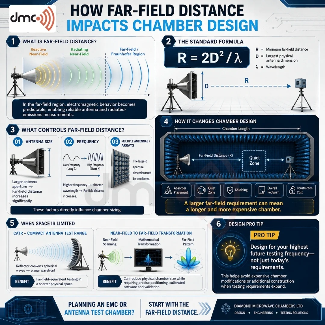
Electromagnetic radiation from any antenna passes through three distinct zones as it propagates outward: the reactive near-field, the radiating near-field (Fresnel region), and the far-field (Fraunhofer region). In the far-field, the wavefront behaves as though it originates from a single point source, and the field pattern stabilizes into a predictable shape that no longer changes with additional distance. This is the region where accurate antenna pattern measurements, gain calculations, and radiated emissions testing can actually be trusted.
Inside the near-field, the relationship between electric and magnetic field components is unstable and highly dependent on exact position. Measurements taken here do not represent how the antenna will actually perform in real-world use, which is precisely why chamber designers work hard to push the test setup into the far-field region.
The Standard Far-Field Formula
The most widely used far-field distance calculation is the Fraunhofer distance formula:
R = 2D² / λ
Where R is the minimum far-field distance, D is the largest physical dimension of the antenna, and λ is the wavelength of the signal being tested. This formula shows immediately why far-field distance is not a static number: it scales with the square of the antenna’s size and inversely with wavelength. A small antenna operating at a low frequency may reach far-field conditions within a meter, while a large phased array antenna operating at high frequency can require a far-field distance stretching well beyond what a standard chamber can physically house.
Why This Matters for Chamber Design
Chamber designers cannot simply build a large box and call it done. The far-field distance calculation directly drives multiple physical and engineering decisions:
- Chamber length: The distance between the antenna under test and the receiving antenna or field probe must meet or exceed the calculated far-field requirement.
- Absorber selection and placement: Longer chambers require pyramidal or hybrid absorbers tuned to specific frequency ranges to suppress reflections along the extended path.
- Quiet zone size: The usable test volume where field uniformity is guaranteed shrinks or expands based on how far the antenna sits from the test boundary.
- Cost and footprint: Larger far-field requirements mean more absorber material, more shielding, and a bigger physical structure, all of which raise construction cost.
- Compact range feasibility: When far-field distance exceeds practical chamber dimensions, designers may need to incorporate a compact antenna test range (CATR) using a reflector to simulate far-field conditions in a shorter physical space.
Each of these decisions compounds. A miscalculated far-field distance at the design phase can mean a chamber that fails to deliver reliable, repeatable test data even after full construction, which is a costly mistake to discover after the fact.
Frequency and Antenna Size: The Two Biggest Variables
| Factor | Effect on Far-Field Distance | Design Implication |
|---|---|---|
| Higher frequency (shorter wavelength) | Increases far-field distance | Requires longer chamber or CATR solution |
| Lower frequency (longer wavelength) | Decreases far-field distance | Allows more compact chamber design |
| Larger antenna aperture | Increases far-field distance significantly (squared relationship) | Major driver of chamber length requirements |
| Smaller antenna aperture | Decreases far-field distance | Enables smaller, cost-effective chambers |
| Multiple antennas / arrays | Uses largest aperture dimension for calculation | Can force unexpectedly large chamber sizing |
This table highlights why two chambers built for seemingly similar purposes can differ drastically in size. A chamber designed for millimeter-wave 5G testing with large array antennas will need far more length than one designed for lower-frequency IoT device compliance testing.
Compact Range Solutions When Space Is Limited
Not every facility has the physical space to accommodate a true far-field distance, especially for high-frequency, large-aperture applications. This is where compact range technology becomes valuable. A parabolic or shaped reflector is used to convert a spherical wavefront from the feed antenna into a planar wavefront, effectively simulating far-field conditions within a much shorter physical chamber. Diamond Microwave Chambers Ltd designs compact range chambers specifically for organizations that need far-field-equivalent accuracy without the enormous footprint a traditional far-field chamber would demand.
Near-Field to Far-Field Transformation
Another approach gaining traction, particularly for antenna characterization, is near-field scanning combined with mathematical transformation. Field data is collected close to the antenna using planar, cylindrical, or spherical scanning techniques, and then computational transforms calculate what the far-field pattern would be. This method reduces physical chamber size requirements but demands precise positioning systems and calibrated software, along with rigorous validation to confirm the transformed data matches expected far-field behavior.
Pro Tip
Always calculate far-field distance using the highest frequency your test plan will ever require, not just your current testing needs. Chambers are long-term capital investments, and designing only for today’s frequency range often means an expensive retrofit or a second chamber build within a few years as testing requirements shift toward higher frequencies.
Getting Chamber Design Right From the Start
Far-field distance is not a detail to work around after the chamber is built; it is the calculation that determines whether the chamber will work at all for its intended purpose. Every dimension, every piece of absorber, and every claim about quiet zone accuracy traces back to this figure. Diamond Microwave Chambers Ltd approaches chamber design by starting with the customer’s full frequency range and antenna specifications, running the far-field calculations first, and only then moving into absorber selection, shielding design, and construction planning. This sequence protects customers from the costly mistake of a chamber that looks complete but cannot deliver trustworthy measurement data.
Organizations evaluating a new antenna test chamber should treat far-field distance as their first question, not their last. Getting it right from day one is the difference between a facility that delivers accurate, repeatable results for decades and one that requires expensive rework within its first few years of operation.
Frequently Asked Questions
The standard formula is R = 2D² / λ, where R is the far-field distance, D is the largest antenna dimension, and λ is the wavelength. This determines the minimum distance needed between the antenna and test point for accurate measurements.
Near-field measurements are unstable and highly position-dependent because the electric and magnetic field relationship has not yet stabilized. Results taken here do not accurately reflect how the antenna performs in real-world far-field conditions.
The measurements will not represent true far-field antenna behavior, leading to inaccurate gain readings, distorted radiation patterns, and unreliable compliance test results, even though the chamber may appear fully functional.
A CATR uses a reflector to convert a spherical wavefront into a planar one, simulating far-field conditions within a shorter chamber. It is used when true far-field distance requirements exceed available physical space.
Antenna size has a squared effect on far-field distance (D²), making it the dominant factor. However, higher frequency (shorter wavelength) also increases the required distance, so both variables must be evaluated together.