How to Characterize Near Field Test Range in RF Anechoic Chamber?
RF anechoic chambers are essential facilities for performing accurate electromagnetic (EM) measurements, especially antenna characterization and EMC testing. When it comes to near field measurements, understanding how to properly characterize the near field test range in an RF anechoic chamber is critical for ensuring reliable results. In this blog, we will discuss the concept of near field test range characterization, its importance, steps involved, and key considerations to maintain measurement integrity.
What is Near Field Test Range Characterization?
Characterization of the near field test range involves defining, verifying, and documenting the performance of the measurement setup within the RF anechoic chamber. Unlike far field measurements where the antenna’s radiation pattern is directly assessed at distances satisfying far field conditions, near field characterization involves measuring EM fields close to the antenna under test (AUT) and mathematically transforming them into far field results using near-to-far field transformation techniques.
Why Characterize Near Field Test Range?
- Ensure measurement accuracy:
Characterization identifies setup errors, reflections, or chamber imperfections that affect results. - Compliance with standards:
EMCand antenna testing standards (IEEE, CISPR, ETSI) require system characterization for calibration and validation. - System performance verification:
Confirming that the probe, positioner, and chamber are working within expected performance ranges. - Baseline documentation:
Helps create traceable data for future comparison or troubleshooting.
Steps to Characterize Near Field Test Range
1.Understand the Measurement Setup
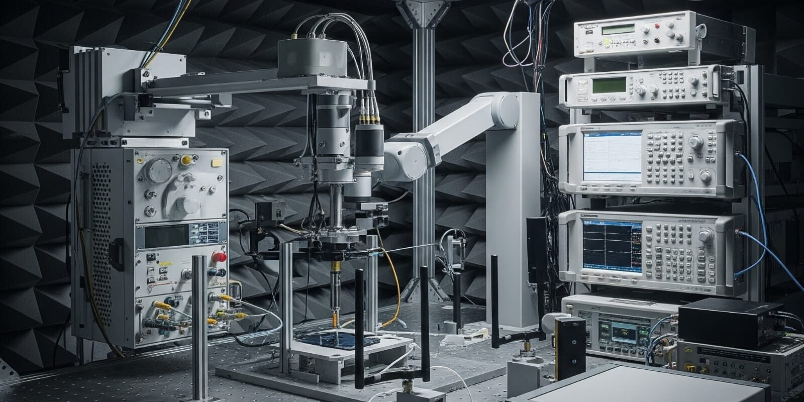
Near field test setups typically include:
- AUT (Antenna Under Test)mounted on a positioner.
- Probe systemto measure EM fields in planar, cylindrical, or spherical scanning geometries.
- RF receiver and controllerfor data acquisition.
- Anechoic chamberto suppress reflections and external interference.
2. Define the Measurement Volume
Determine the spatial volume around the AUT to be scanned based on:
- Antenna size
- Operating frequency
- Required resolution
For example, a planar scan must cover the entire aperture of the antenna plus margin to accurately transform to far field.
3. Perform System Calibration
Calibration ensures the measurement probe, cables, positioners, and receivers are characterized for amplitude and phase accuracy.
- Use known calibration standards or reference antennas.
- Calibrate probe patterns and gain using known signal sources.
- Measure and compensate positioner alignment errors.
4.Validate Chamber Performance
- Reflection coefficient (VSWR) test:Verify chamber absorbers provide sufficient reflectivity reduction within the frequency band.
- Quiet zone verification:Measure residual field levels without AUT transmission to ensure minimal background noise or reflections.

Near Field Test Range in RF Anechoic Chamber img
5. Conduct Test Measurements
Measure a well-known reference antenna’s near field to validate:
- Transformation algorithms
- Data acquisition accuracy
- Setup repeatability
Compare the measured far field pattern (via near-to-far field transformation) with published data of the reference antenna to confirm system performance.
6. Analyze and Document Results
- Record calibration factors, measurement uncertainties, chamber validation results, and system configurations.
- Maintain structured documentation for compliance audits or future tests.
Key Considerations in Near Field Characterization
✔ Probe positioning accuracy – critical for phase-sensitive measurements
✔ Environmental control – temperature variations affect electronics
✔ Absorber performance – degraded absorbers increase reflections
✔ Frequency range limitations – ensure probe and chamber are rated for test frequencies
✔ Software validation – transformation algorithms must be verified for accuracy
Near Field vs Far Field Testing
|
Near Field Testing |
Far Field Testing |
|
Performed close to AUT (typically < λ²/D) |
Performed at distances > 2D²/λ |
|
Requires near-to-far field transformation |
Direct far field measurement |
|
Enables compact test ranges |
Requires larger chamber or outdoor range |
|
Complex calibration |
Simpler setup |
Where λ is wavelength and D is the maximum dimension of AUT.
Characterizing the near field test range in an RF anechoic chamber is an essential process to ensure accurate antenna measurements and EMC compliance. By following systematic calibration, validation, and documentation procedures, engineers can maximize the accuracy of their measurements and the credibility of their test results.
FAQs
1. What is the purpose of near field characterization?
Near field characterization ensures that measurement setups yield accurate results by calibrating and validating the system for electromagnetic tests within an RF anechoic chamber.
2. What equipment is needed for near-field test range characterization?
Equipment includes the AUT, positioners, measurement probes, RF receivers, calibration standards, and the anechoic chamber itself.
3. What is near-to-far field transformation?
It is a mathematical process to convert near field data measured close to the antenna into equivalent far field radiation patterns.
4. How often should near field test range characterization be performed?
Typically, during initial setup, after any hardware changes, or at defined calibration intervals as per lab quality systems.
5. What are common errors in near field measurements?
Errors include probe misalignment, positioner inaccuracies, poor chamber reflectivity, and incorrect transformation algorithm settings.

