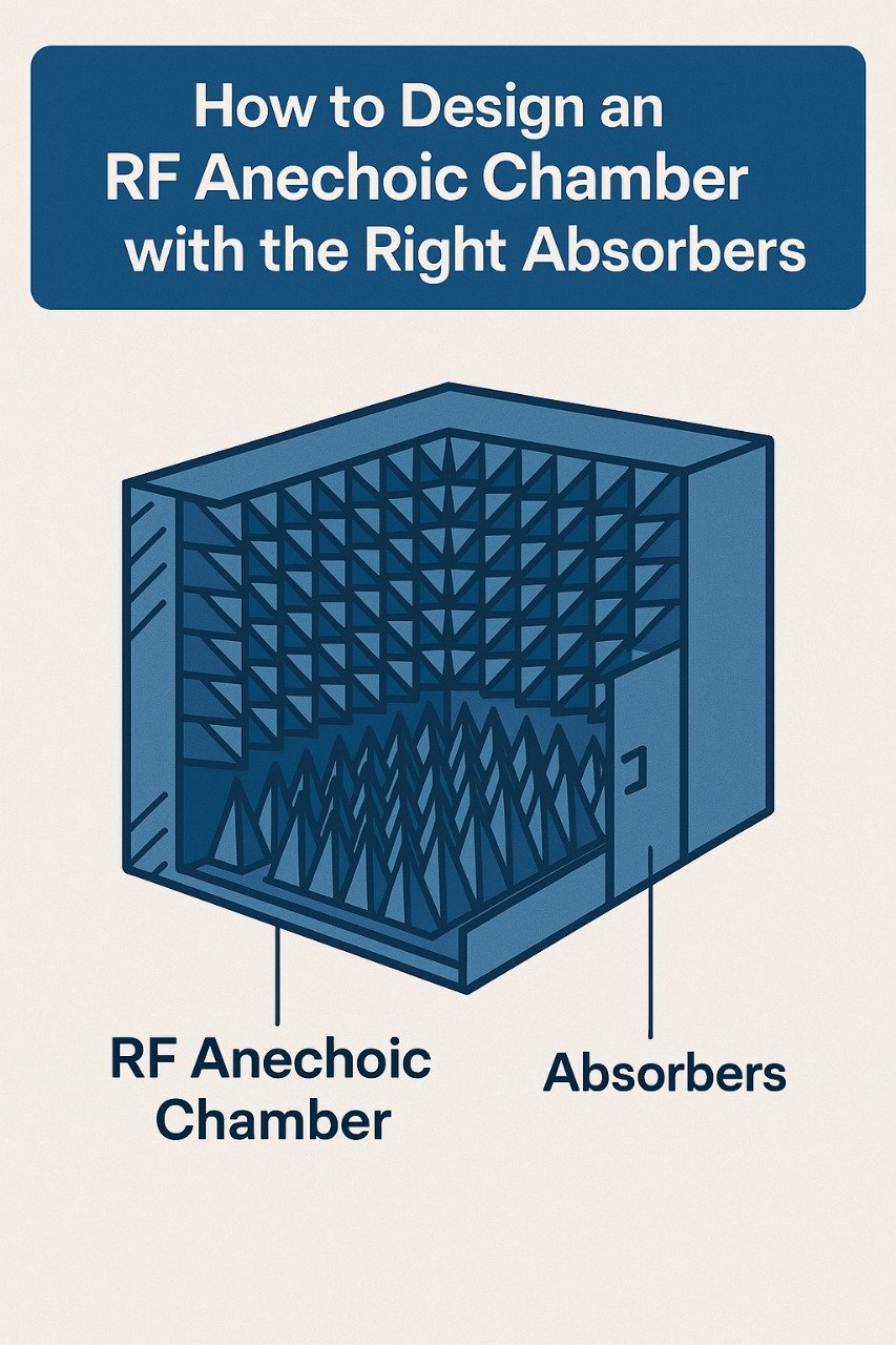
Designing an RF anechoic chamber is a critical task for any organisation involved in antenna measurements, EMC testing, radar cross-section analysis, or wireless device development. A well-designed chamber ensures that measurements are accurate, repeatable, and compliant with global standards. One of the most important aspects of chamber design is selecting the right RF absorbers. Let’s explore how to design an effective RF anechoic chamber with appropriate absorber solutions.
What is an RF Anechoic Chamber?
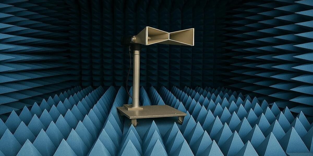
An RF anechoic chamber is a shielded room lined with RF absorbers to prevent electromagnetic waves from reflecting back to the device under test (DUT). This creates a controlled free-space environment, isolating the DUT from external RF noise and internal reflections. Such chambers are vital for testing antennas, radars, wireless devices, and electronic equipment under standardised conditions.
Step 1: Define Your Testing Requirements
Before starting the design process, clearly define your chamber’s purpose:
- Frequency range: Determine the lowest and highest frequencies to be tested. For example, EMC chambers usually require performance from 30 MHz upwards, while antenna test ranges may go up to 40 GHz or higher.
- Device size and quiet zone: Consider the dimensions of the DUT and required quiet zone (the area with minimal reflections for accurate testing). Larger DUTs require bigger quiet zones and chamber sizes.
- Test types: Decide whether it’s for EMC compliance, antenna pattern measurements, or radar cross-section tests, as each has unique absorber performance needs.
Step 2: Calculate the Chamber Size
Chamber size is dictated by:
- The far-field distance for antenna testing (calculated using 2D²/λ).
- The absorber layout, ensuring sufficient thickness without encroaching on test distances.
- Practical factors such as equipment movement, operator space, and maintenance access.
A well-sized chamber reduces unwanted reflections and allows correct placement of absorbers to maximise their effectiveness.
Step 3: Select the Right RF Absorbers
Choosing appropriate absorbers is crucial. The types include:
Ferrite Tile Absorbers
- Effective at low frequencies (30 MHz to 1 GHz).
- Consist of ferrite ceramic tiles mounted on walls, ceiling, and sometimes floor.
- Ideal for EMC chambers where low-frequency absorption is mandatory.
Pyramidal Foam Absorbers
- Typically used for frequencies above 500 MHz up to 100 GHz.
- Made from carbon-loaded foam shaped into pyramids to increase surface area and attenuation.
- Longer pyramids absorb lower frequencies better, while shorter pyramids are used for higher frequencies.
Hybrid Absorbers
- Combine ferrite tiles with pyramidal foam absorbers to cover a broad frequency range (30 MHz – 40 GHz).
- Common in chambers that need low-frequency performance and wideband high-frequency absorption for EMC, antenna, and radar testing.

Design an RF Anechoic Chamber
Step 4: Assess Reflectivity Requirements
Absorber performance is measured by its reflectivity in dB. The lower the reflectivity, the better the absorber prevents signal reflections. For precision antenna testing, absorbers with -40 dB reflectivity or lower at target frequencies are ideal. EMC testing standards typically require at least -20 dB at the lowest frequency.
Step 5: Plan the Layout and Installation
Proper installation is as important as absorber selection. Ensure:
- No gaps between absorbers to avoid leakage or reflections.
- Correct orientation of pyramidal absorbers for maximum performance.
- Secure fixing methods to withstand temperature changes and vibrations over time.
- Floor absorbers are load-bearing if heavy equipment will be used inside the chamber.
Step 6: Comply with Safety and Standards
Always use absorbers with proven fire-retardant properties and compliance certifications for your application (e.g., UL94). Ensure the entire chamber design adheres to relevant standards like CISPR, IEEE, or MIL-STD, depending on your testing needs.
Benefits of Choosing the Right Absorbers
✅ Accurate Measurements
Eliminate errors caused by unwanted reflections, leading to precise data.
✅ Standard Compliance
Meet EMC, antenna, and radar testing standards with ease.
✅ Cost Efficiency
Reduce retesting costs and delays with reliable chamber performance.
✅ Future-Proofing
Selecting high-quality broadband absorbers supports the testing of new technologies without the need for frequent upgrades.
Designing an RF anechoic chamber is a significant investment for any research lab or manufacturing facility. The absorbers you choose will define the chamber’s performance, reliability, and lifespan. Always work with experienced RF chamber designers and reputable absorber manufacturers to create a solution tailored to your specific testing applications.
Suppose you’re planning to design or upgrade an RF anechoic chamber. In that case, our team of RF engineering experts can guide you through absorber selection, chamber design optimisation, and installation for the highest accuracy and compliance.
🛠️ Ready to design or upgrade your RF anechoic chamber?
Contact us today for expert solutions in absorber selection, chamber design, and turnkey installation.

