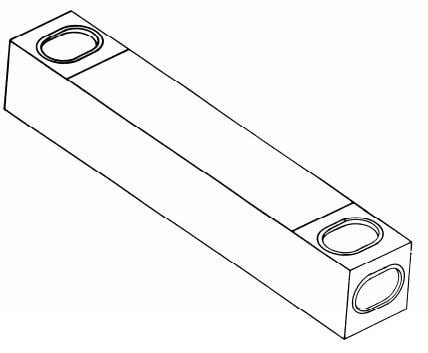
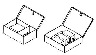
The filter herein described shall be designed for filtering of radio frequency interference and to meet the requirements of Military Specifications MIL-F-15733, where applicable. These filters may be used with other electrical devices to enable the devices to meet the requirements of MIL-I-26600, MIL-I-16910. MIL-I- 6181, MIL-I-11748, MIL-STD-461, 462, 463, FED-STD-222 and FCC Specification Part 18. Also, DCA specifications and others developed for special equipment and systems applications


| DMC Part No | Maximum Current Amperes | Maximum Line-to-ground Voltage | Power Line Frequency (Hz) | Dimensions | Approx. Wt. (Lbs.) | |||
| AC | DC | A | B | C | ||||
| DMC-FCL·14-25 | 25 | 277 | 600 | 0-60 | 18 ¼ | 4 | 4 ¼ | 13 |
| DMC-FCL·14·50 | 50 | 277 | 600 | 0-60 | 18 ¼ | 4 | 4 ¼ | 13 |
| DMC-FCL·14·100 | 100 | 277 | 600 | 0-60 | 18 ¼ | 4 | 4 ¼ | 13 |
| DMC-FCL·14-200 | 200 | 277 | 600 | 0-60 | 18 ¼ | 4 | 4 ¼ | 13 |
| DMC-FCL·140-25 | 25 | 277 | 600 | 0-400 | 18 ¼ | 4 | 4 ¼ | 13 |
| DC-FCL·140-50 | 50 | 277 | 600 | 0-400 | 18 ¼ | 4 | 4 ¼ | 13 |
| DMC-FCL·140-100 | 100 | 277 | 600 | 0-400 | 18 ¼ | 4 | 4 ¼ | 13 |
|
DMC-Part No |
Maximum Current (Amps) | Maximum Voltage | Power Line Frequency (Hz) |
Dimensions
A B C |
Approx. WT
(Lbs.) |
||
| VAC | VDC | ||||||
| Line-to-
ground |
Line-
to-line |
||||||
| DMC-FCL·112·25 | 25 | 277 | 480 | 800 | 60 | 34 4 ½ 4 ½ | 20 |
| DMC-FCL·112·50 | 50 | 277 | 480 | 800 | 60 | 34 4 ½ 4 ¾ | 25 |
| DMC-FCL·112·10 | 100 | 277 | 480 | 800 | 60 | 40 9 5 | 30 |
| DMC-FCL·112·15 | 150 | 277 | 480 | 800 | 60 | 40 15 5 ¼ | 60 |
| DMC-FCL·112·2O | 200 | 277 | 480 | 800 | 60 | 40 15 5 ¼ | 60 |
These filters are suitable for use in 3·phase systems up to 480 volts phase-to-phase Filters for 400 Hz power available upon request.
Specifications
GENERAL
The filter herein described shall be designed for filtering of radio frequency interference and to meet the requirements of Military Specifications MIL-F-15733, where applicable. These filters may be used with other electrical devices to enable the devices to meet the requirements of MIL-I-26600, MIL-I-16910. MIL-I- 6181, MIL-I-11748, MIL-STD-461, 462, 463, FED-STD-222 and FCC Specification Part 18. Also, DCA specifications and others developed for special equipment and systems applications
ELECTRICAL
CURRENT RATING: The filters shall be capable of withstanding 150% of rated current for 15 minutes without any deterioration.
INSERTION LOSS: The filter shall provide the specified insertion loss of 100 db minimum over its indicated frequency range when measured in accordance with the applicable MIL-STD-220A by a government approved laboratory.
VOLTAGE: The filters shall be capable of operating continuously at full- rated voltage and of withstanding an initial voltage test of twice the rated voltage for one minute.
MECHANICAL
CASE: The filter case shall be made of cold-rolled steel.
CONSTRUCTION: Input and output terminals shall be completely enclosed in RF shielded compartments. Covers on the input and output RF shielded compartments shall be friction-fitted. Internal components shall be mounted and fixed to prevent damage when subjected to shock and vibration tests.
FINISH: All filter cases shall be made corrosion-resistant with suitable lacquer over primer, All unfinished grounding surfaces shall be protected by suitable plating.
IMPREGNANT: The impre9nant shall be non-flammable as classified by Underwriters Laboratories.
TERMINALS: The terminals shall be made of high temperature alumina ceramic. The ceramic terminal shall have a flexible insulated lead, one end of which is permanently affixed to the terminal, The other end shall be terminated in a permanently affixed lug which shall be mounted on approved flame-retardant insulator.
