Made in USA
UL Listed

Military EMI Filters

These Filters are available in two series

DMC-FC 00-W:  100dB attenuation from 14 kHz to 10 GHz measured per MIL-STD-220A full load

DMC-FC 00-X:  100dB attenuation from 14 kHz to 10 GHz measured per MIL-STD-220A full load. SPECIAL: Measured from 14 kHz to 20 MHz under full load condition with extended range buffer network

HIGHLIGHTS: High reliability. Special design and construction developed for secure communication areas, tempest shielded rooms. Designed for many years of continuous fail free service. All filters are field replaceable.

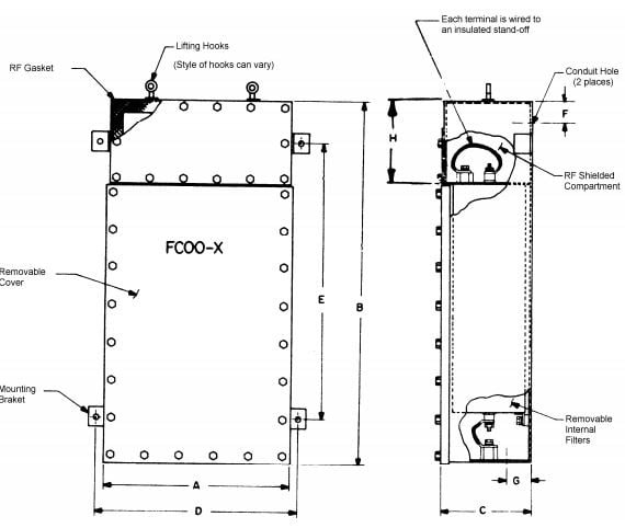
SERIES DMC-FC 00-X

PART NO. CURRENT (AMPERES) DIMENSIONS (INCHES) CONDUIT
ENTRY DIA.
APPROX.
WEIGHT (LBS.)
A B C D E F G H
DMC-FC00·X·2×5 2×5 12 ¼ 29 5 14 ¼ 17 2 2 5.75  7/8 75
DMC-FC00-X-3×5 3×5 20 29 5 22 17 2 2 5.75  7/8 110
DMC-FC00-X-4×5 4×5 20 29 5 22 17 2 2 5.75  7/8 130
DMC-FC00-X-2×30 2×30 12 ¼ 37 5 14 ¼ 25 3 2 4.25 1 3/8 135
DMC-FC00-X-3×30 3×30 20 37 5 22 25 3 2 4.25 1 3/8 165
DMC-FC00-X-4×30 4×30 20 37 5 22 25 3 2 4.25 1 3/8 200
DMC-FC00-X-2×60 2×60 15 ½ 48 11 17 ½ 36 3 5 9.38 1 ¾ 230
DMC-FC00-X-3×60 3×60 25 48 11 27 36 3 5 9.38 1 ¾ 320
DMC-FC00-X-4×60 4×60 25 48 11 27 36 3 5 9.38 1 ¾ 380
DMC-FC00-X-2×100 2×100 16 ½ 60 11 18 ½ 48 4 5 9.38 2 290
DMC-FC00-X-3×100 3×100 25 60 11 27 48 4 5 9.38 2 400
DMC-FC00-X-4×100 4×100 25 60 11 27 48 4 5 9.38 2 450
DMC-FC00-X-2×200 2×200 17 ½ 60 25 19 ½ 48 4 5 10 3 600
DMC-FC00-X-3×200 3×200 25 60 25 27 48 4 5 10 3 750
DMC-FC00-X-4×200 4×200 25 60 25 27 48 4 5 10 3 900
DMC-FC00-X-4×300 4×300 50 60 25 54 48 4 5 10 3 900

SERIES DMC- FC 00-W (FC 00-W has one piece cover)


PART NO.

CURRENT (AMPERES) DIMENSIONS (INCHES)

CONDUIT

ENTRY DIA.

APPROX.

WEIGHT (LBS.)

A B C D E F G H
DMC-FC00·W·2×5 2×5 12 ¼ 29 5 14 ¼ 17 2 2 5.75 7/8 75
DMC-FC00-W-3×5 3×5 20 29 5 22 17 2 2 5.75 7/8 105
DMC-FC00-W-4×5 4×5 20 29 5 22 17 2 2 5.75 7/8 125
DMC-FC00-W-2×30 2×30 12 ¼ 37 5 14 ¼ 25 3 2 7.75 1 3/8 80
DMC-FC00-W-3×30 3×30 20 37 5 22 25 3 2 7.75 1 3/8 130
DMC-FC00-W-4×30 4×30 20 37 5 22 25 3 2 7.75 1 3/8 165
DMC-FC00-W-2×60 2×60 15 ½ 37 5 18 ½ 25 3 2 7.75 1 ¾ 100
DMC-FC00-W-3×60 3×60 20 37 5 27 25 3 2 7.75 1 ¾ 140
DMC-FC00-W-4×60 4×60 20 37 5 27 25 3 2 7.75 1 ¾ 175
DMC-FC00-W-2×100 2×100 16 ½ 37 11 18 ½ 25 5 5 10.00 2 170
DMC-FC00-W-3×100 3×100 25 37 11 27 25 5 5 10.00 2 250
DMC-FC00-W-4×100 4×100 25 37 11 27 25 5 5 10.00 2 300
DMC-FC00-W-2×200 2×200 17 ½ 40 17 19 ½ 28 5 5 10.00 3 200
DMC-FC00-W-3×200 3×200 25 40 17 27 28 5 5 10.00 3 350
DMC-FC00-W-4×200 4×200 25 40 17 27 28 5 5 10.00 3 425
DMC-FC00-W-4×300 4×300 50 40 17 54 28 5 5 10.00 3 425

These models are available with NT suffix denoting grounded neutral terminal in case.

All filters above are rated for 0-60 Hz line frequencies. 400 Hz power filters are available. Voltage rating: 0-277 VAC line-to-neutral or 0-480 VAC line-to-line, 600 VDC max Single filter is available in cabinet for above series.

Specifications

GENERAL

The filter herein described shall be designed for filtering of radio frequency interference and to meet the requirements of Military Specifications MIL-F-15733, where applicable. These filters may be used with other electrical devices to enable the devices to meet the requirements of MIL-I-26600, MIL-I-16910, MIL-I-6181, MIL-I-11748, MIL-STO-461, 462, 463, FED-STD-222,

And FCC Specification. Also, DCA specifications and others developed for special equipment and systems applications.


ELECTRICAL

CURRENT RATING: The filters shall be capable of carrying full-rated current with a heat rise not exceeding 25°C above ambient temperature. The filters shall be capable of withstanding 150% of rated current overload for 15 minutes without any deterioration.


VOLTAGE: The filters shall be capable of operating continuously at full-rated voltage and of withstanding an over-voltage test of twice the rated voltage for one minute. Maximum voltage drop shall not exceed 2 volts when measured in accordance with MIL-F-15733. Maximum operating temperature: 85°C.


MECHANICAL

CASE: The inner cases of each filter shall be made of C.R.S. 16 GA. min. Each phase filter shall be individually replaceable. All internal filters are hermetically sealed.


TERMINALS: The Military EMI Filters shall be made of high temperature alumina ceramic and shall be leak proofed. The ceramic terminal shall have a flexible insulated lead, one end of which is permanently attached to the terminal, the other end in a permanently affixed lug mounted on .7 approved flame-retardant stand-off insulator secured with a suitable screw. All connections shall be made only at the stand-offs.


IMPREGNANT: Where applicable the Impregnant shall be non-flammable as classified by U.L. and MIL-F-15733.

CONSTRUCTION: Input and output terminals shall be completely enclosed in Military EMI Filters. Covers on the input and output RF shielded compartments shall be held down with screws,  Gasketing shall be used between the cover and the inside fitting flange to maintain Military EMI Filters. Internal components shall be mounted and fixed to prevent damage when subjected to applicable shock and vibration tests.


FINISH: All filter cases shall be made rust proof by painting over primer. All unfinished grounding surfaces are protected by suitable plating.