- Filters are listed per UL specification #1283
- Temperature Range: Operating -55°C to +85°C
- Enclosures are made from cold rolled steel with continuously welded seams
- Filter ground path connecting surfaces shall be tin plated or stainless steel
- Conduit hubs or clearance holes may be provided if specified when ordering
- Each phase filter is individually removable
- Internal filters are filed with a non-flammable impregnant and hermetically sealed
- Legs for floor mounting may be provided if specified when ordering
- Filters for 300AMP and up have 6” x 2” mounting U-Channel


HEMP Filters
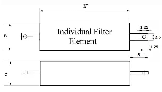
Series DMC-FCHS-HEMP Single Individual Filter Elements

Specifications
ELECTRICAL
CURRENT RATING: The filters shall be capable of withstanding 140% of rated current for 15 minutes without any deterioration.
INSERTION LOSS: The HEMP Filters shall provide the specified insertion loss of 80 db minimum over its indicated frequency range when measured in accordance with the applicable MIL-STD-220C by a government approved laboratory.
VOLTAGE: The filters shall be capable of operating continuously at full- rated voltage and of withstanding an initial voltage test of twice the rated voltage for one minute.
OPERATING TEMPERATURE
FILTER ELEMENT: Assembly: from 0°F to 104°F (-18°C to 40°C) at rated voltage and full load operations Components: from 0°F to 150°F (-18°C to 65°C) at rated voltage and full load operation
MECHANICAL
CASE: The HEMP Filters case shall be made of cold-rolled steel.
FINISH: All HEMP Filters cases shall be made corrosion-resistant with suitable lacquer over primer, All unfinished grounding surfaces shall be protected by suitable plating.
IMPREGNANT: The impregnant shall be non-flammable as classified by Underwriters Laboratories.
TERMINALS: The terminals shall be made of high temperature alumina ceramic. The ceramic terminal shall have a flexible insulated lead, one end of which is permanently affixed to the terminal, The other end shall be terminated in a permanently affixed lug which shall be mounted on approved flame-retardant insulator.
| Part Number | Current Rating (AMP) | Voltage Rating | Frequency Rating (Hz) | Dimensions (INCHES) | Weight Approx. (LBS) | |||||
| LG / LL VAC | VDC | A±.060 | B±.060 | C±.060 | D±.060 | E±.060 | ||||
| DMC-FCULX-4 X 30E2 HEMP | 4 x 30 | 277 / 480 | 600 | 60 | 28 | 38 | 6 | 64 | 26 | 220 |
| DMC-FCULX-4 X 60E2 HEMP | 4 x 60 | 277 / 480 | 600 | 60 | 28 | 41 | 8 | 64 | 29 | 315 |
| DMC-FCULX-4 X 100E2 HEMP | 4 x 100 | 277 / 480 | 600 | 60 | 57 | 60 | 10 | 80 | 48 | 520 |
| DMC-FCULX-4 X 225E2 HEMP | 4 x 225 | 277 / 480 | 600 | 60 | 28 | 60 | 16 | 64 | 48 | 750 |
| DMC-FCULX-4 X 250E2 HEMP | 4 x 250 | 277 / 480 | 600 | 60 | 28 | 60 | 16 | 64 | 42 | 750 |
| DMC-FCULX-4 X 300E2 HEMP | 4 x 300 | 277 / 480 | 600 | 60 | 60 | 84 | 16 | 66 | 44 | 850 |
| DMC-FCULX-4 X 400E2 HEMP | 4 x 400 | 277 / 480 | 600 | 60 | 60 | 84 | 16 | 66 | 44 | 975 |
| DMC-FCULX-4 X 500E2 HEMP | 4 x 500 | 277 / 480 | 600 | 60 | 60 | 84 | 16 | 66 | 44 | 1075 |
| DMC-FCULX-4 X 600E2 HEMP | 4 x 600 | 277 / 480 | 600 | 60 | 45 | 84 | 34 | 38 | 44 | 1600 |
| DMC-FCULX-4 X 800E2 HEMP | 4 x 800 | 277 / 480 | 600 | 60 | 60 | 72 | 34 | 66 | 44 | 2400 |
| DMC-FCULX-4 X 1000E2 HEMP | 4 x 1000 | 277 / 480 | 600 | 60 | 60 | 72 | 34 | 66 | 44 | 2500 |
| DMC-FCULX-4 X 1200E2 HEMP | 4 x 1200 | 277 / 480 | 600 | 60 | 60 | 72 | 34 | 64 | 44 | 2750 |
| DMC-FCULX-4 X 1500E2 HEMP | 4 x 1500 | 277 / 480 | 600 | 60 | 60 | 72 | 34 | 64 | 44 | 2900 |
*All Filter Cabinets are also available in 3 line and 4 line configuration
| PART NO | CURRENT RATING (AMP) | VOLTAGE RATING (VAC) | FREQ RATING (HZ) | WIRE SIZE | DIMENSION (INCH) | INSERTION LOSS (DB) | ||||||
| A | B | C | 100kHz | 1MHz | 10MHz | 100MHz | 1GHz | |||||
| DMC-FCH-800- E2 | 800 | 277 | 0-60 | 2.5 x 0.5 Bus Bar | 35 | 17 | 14 | 80 | 80 | 80 | 80 | 80 |
| DMC-FCH-400- E2 | 400 | 277 | 0-60 | 250MCM | 32 | 16 | 12 | 80 | 80 | 80 | 80 | 80 |
| DMC-FCH-100- E2 | 100 | 277 | 0-60 | #2 | 30 | 14 | 10 | 80 | 80 | 80 | 80 | 80 |
| DMC-FCH-60- E2 | 60 | 277 | 0-60 | #10 | 28 | 14 | 8 | 80 | 80 | 80 | 80 | 80 |
| DMC-FCH-30- E2 | 30 | 277 | 0-60 | #10 | 28 | 14 | 6 | 80 | 80 | 80 | 80 | 80 |
